external equipment#
Click External Devices to enter the External Devices Configuration page, which contains External Axis Configuration, Adjustment Module Configuration, Traction Module Configuration, and Laser Configuration;
External Axis Configuration#
The External Device Configuration page defaults to external axis configuration
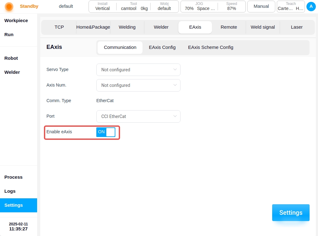
Communication settings
The Communication Settings page allows you to configure the servo model, the number of axes, the input port, and the display of the communication method. The servo model and axis number are not configured by default, the input port is only the Ethercat port of the control cabinet at present, and the communication mode is Ethercat by default.
Choose to configure the servo model, the number of axes, as shown in the figure below, and then click on the “Settings” button, a pop-up message “Setting is successful, restart the control cabinet to take effect! The message will pop up “Setting is successful, restart the control cabinet to take effect!”.

If the topology configured by the user is different from the topology currently in effect on the system, click the “Set” button and a pop-up box will appear in the interface, as shown in the following figure:
If you do not want to modify the topology currently stored in the system, click the “Cancel” button; if you confirm the modification, click the “Confirm” button.
Axis configuration
The Axis Configuration page displays basic information such as axis name, axis type, axis position, etc. It allows you to perform point-to-point movement of the axis position, enable or disable operation of the axis, as well as configuration of the axis parameters. One external axis corresponds to one actual single-degree-of-freedom servo unit.
When the external axis is enabled by clicking the Enable button, the external axis can be moved in the reverse or forward direction by pressing and holding the left  icon or the right
  icon on the axis position display.
Note: When the external axis break is enabled, no axis pointing operation can be performed.
Click the “Configuration” button, the external axis parameter configuration pop-up box will appear as shown in the figure below, the configurable parameters are axis type, axis control mode, reference speed, reference acceleration, The configurable parameters are axis type, axis control mode, reference speed, reference acceleration, maximum speed, maximum acceleration, encoder type, encoder resolution, zero offset, guide range, direction of motion, upper limit position, lower limit position.

Parameter description:
Axis type: Linear guides or translators;
Axis control modes: active control mode or cooperative control mode. In active control mode, the external axes are directly generated and controlled by the robot controller for planning instructions; In cooperative control mode, the external axes are controlled by independent controllers and communicate with the robot controller, and the robot carries out cooperative control based on the external axis commands. The robot maintains a specific relationship with the external axis coordinate system;
Reference speed: This speed will be used as a reference speed in mm/s or °/s for external axis pointing movements;
Reference Acceleration: This acceleration will be used as the reference acceleration in mm/s^2 or °/s^2 for the pointwise motion of the external axis;
Maximum speed: This speed will be used as the maximum speed constraint and monitoring parameter in mm/s or °/s for the joint planning of movements of external axes;
Maximum acceleration: This acceleration will be used as a parameter for acceleration constraints and monitoring during the joint planning of the movement of the external axes, in mm/s^2 or °/s^2;
Encoder type: incremental or absolute;
Encoder resolution: a dimensionless parameter used to convert the number of encoder communication data cnt into a scale factor of the actual angle value, encoder cnt/number of encoder bits = actual angle;
Zero Offset: only shows configurable and effective if the encoder type is absolute, default is 0, unit is mm or °, user can modify it directly or quickly by setting the current position as zero position;
Lead: Configurable and valid only if the external axis type is a linear guide, in mm, describes the displacement distance of the linear guide when the encoder is rotated by 360°, encoder cnt/encoder position * lead = actual position of the linear guide;
Direction of motion: Forward or reverse, describes the relationship between the encoder’s increasing direction and the actual shaft’s direction of motion, forward is the same direction, reverse is the opposite reverse;
Upper limit/lower limit: to describe the absolute range of motion of the external axis with reference to the current zero position, exceeding the limit will trigger the corresponding safety stop operation in mm or °.
Note: Configuration of external axis parameters is not possible after the external axis is enabled.
Programme configuration
The Program Configuration page allows you to create a new external axis program, as well as edit or delete an existing external axis program. On the left side of the page is the external axis scheme navigation tab, on the right side of the page is the external axis scheme parameter content corresponding to the external axis scheme tab, as well as all enable/disable buttons, external axis calibration, external axis tap buttons. On the right side of the page are the parameters of the external axis scheme corresponding to the external axis scheme tabs, as well as the buttons for All Enable/Disable, External Axis Calibration, External Axis Tap, and you can manually input the target position of the external axis, and so on. You can also enter the target position of the external axis manually by long-pressing the “Press and hold to move” button to move it to the manually entered target position.

Clicking on the  icon in the upper right corner of the left section of the page will bring up the virtual keyboard as follows:

After entering the name of the newly created external axis scheme, such as “scheme_test” as shown in the figure below, the left navigation tab area will display the name of the newly created external axis scheme “scheme_test”, the color of the font is red, which means that the scheme is invalid, i.e. it is a scheme that has not been configured with the external axis scheme parameters. If the font color is red, it means that the external axis scheme is invalid, i.e., it is a scheme that has not been configured with external axis scheme parameters. Only when the font color is black, it means the external axis scheme is valid. The content area on the right side displays the content that needs to be configured for this new external axis scheme. The parameters that can be configured are: scheme type, degree of freedom configuration, axis-robot relationship, and synchronized robot enable.

Parameter description:
Type of program: Linear guide program or indexing machine program;
Degree of Freedom Configuration: The linear guide program currently supports only single degree of freedom, and the variator program supports single degree of freedom and two degrees of freedom. After selecting the degree of freedom, you can bind the degree of freedom to the external axis according to the number of degrees of freedom selected. As shown in the figure below, the single degree of freedom linear guide program degrees of freedom 1 bound linear guide external axis eaxis_3;
Axis-robot relationship: independent or combined, i.e., the external axis is independent of the robot or the robot is fixed to the external axis;
Note: Axis-robot combinations only support single-degree-of-freedom external axes.
Synchronized Robot Enable: default is not synchronized, if configured as “Synchronized”, the external axis scheme will be synchronized to the enable/disable operation after the robot is enabled/disabled; Scheme base coordinate system: it is used to describe the position of the external axis base coordinate system in the world coordinate system, by default, it coincides with the world coordinate system, which is calibrated through the external axis calibration process. After configuring the above configurable parameters, as shown in the figure below, you can click the “OK” button at the bottom right corner of the page to complete the configuration of the external axis scheme.

In the external axis scheme editing state, the “Enable All” or “Disable All” and “External Axis Calibration” buttons on the page are disabled, and the external axis tap operation buttons are inoperable. The External Axis Push buttons cannot be operated; External axis program enable/disable operations and external axis calibration are only available when the external axis program is not edited. The external axis tap buttons can only be operated when the external axis scheme is enabled, i.e. all external axes are enabled for tap operation.
Clicking on the  icon after the external axis scheme name on the left side of the page will bring up a popup box that displays “Edit” and “Delete” buttons, allowing you to edit or delete the selected external axis scheme.

External axis calibration
The external axis calibration process is used to calibrate the base coordinate system of the external axis scheme. In the non-editing state of the external axis program, click the “External Axis Calibration” button on the page to enter the external axis calibration process page. According to the different types of external axes, the external axis calibration is also divided into two types: linear guide calibration and indexer calibration.
Linear guide calibration#
Depending on the type of relationship between the axes and the robot, there are two types of linear guideway calibration: combined and independent. Here we take the external axis program “scheme_test” as an example to introduce the calibration process of the combined linear guide program. Click on the “External Axis Calibration” button on the page as shown in the figure below:
Determine the zero point: You can press and hold the icons on the left and right sides of the external axis position display to move the external axis, determine the zero point position of the external axis, and then click the “Next” button;
Initial reference point: P1 point is a fixed point outside the robot and external axis, respectively JOG external axis and the robot, so that the end of the robot and the P1 point pasted and recorded; after teaching the robot or external axis position, the P1 point is displayed as
 from
from  , and then click on the “Next” button;
Degree of freedom 1 calibration: Similarly, JOG the external axis with the robot, so that the end of the robot and the P2 point (in the physical environment, that is, the original P1 point) affixed to the record; demonstration of teaching and record the robot end position points, click “Finish”.

Shifter Calibration#
When the external axis type is a shifter, the external axis calibration is the shifter calibration. Here we take the external axis solution of single-degree-of-freedom indexer type as an example to introduce the calibration process of the indexer solution. Click on the “External Axis Calibration” button on the page as shown below:
Determine the zero point: You can press and hold the icons on the left and right sides of the external axis position display to move the external axis, determine the zero point position of the external axis, and then click the “Next” button;
Degree of freedom 1 calibration: P1, P2, P3 are any point on the surface of the external axis, JOG the external axis and the robot, so that the robot end and P1, P2, P3 points were affixed to the merger record; demonstration of teaching and record the robot end position points, click on the “Finish” can be.
External axis programming function block
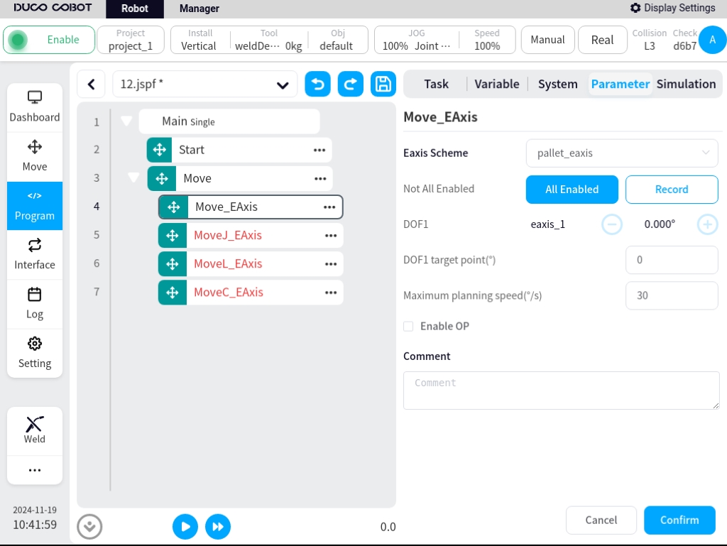
There are four function blocks related to external axes: Move_Eaxis, MoveJ_Eaxis, MoveL_Eaxis, and MoveC_Eaxis.
Move_Eaxis
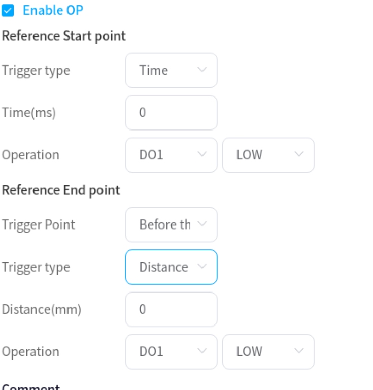
Command block for separate movement of external axes. Parameters can be set: External axis program: name of the target external axis program. Degree of freedom target point: the position of the degree of freedom corresponding to the target external axis program, the recorded position degree of freedom and unit are changed according to the degree of freedom set by the external axis program and the type of the external axis program, the unit is ° or mm. Maximum Planning Speed: Maximum planning speed of the external axis, changed according to the type of the corresponding external axis scheme, in °/s or mm/s. Enable OP: The OP function allows you to set the status of the general-purpose digital output port or operate customized events during trajectory execution.
If OP is enabled, the following configuration is required:
Can be triggered after the start of the trajectory and before/after the end of the trajectory
Trigger type: can choose no trigger, time trigger, distance trigger
Trigger delay: Setting time, unit ms
Trigger distance: set the distance, unit mm
Trigger action: select the port and port status, or operate a customized event
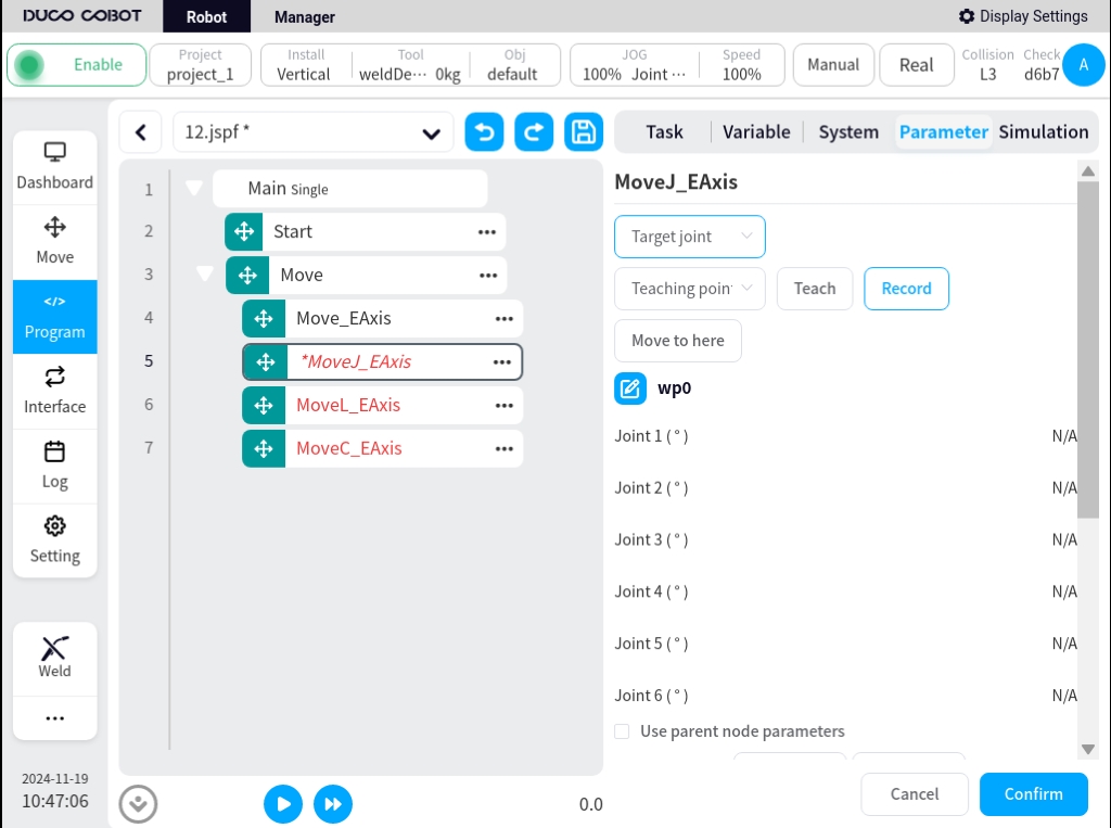
MoveJ_Eaxis
External axis and robot joint motion. The robot moves according to the joint motion and can choose to move to a target joint or a target pose. Parameters can be set: Target position: can be set by means of demonstration or set as a variable, and can be changed manually after the demonstration is set. Use parent node coordinate system: can be set when selecting the target position, when checked, this function block uses the reference coordinate system set by the parent node Move function block, default is checked. Reference coordinate system: can be set when selecting target position attitude, when the Use parent node coordinate system is unchecked, you can set the reference coordinate system for this function block separately. Use parent node parameters: when checked, this function block uses the parameters of joint angular velocity and joint angular acceleration set by the parent node Move function block; when unchecked, you need to set the joint angular velocity and joint angular acceleration for this function block individually, checked by default. Joint angular velocity: unit °/s, you can directly input or select the variable. Joint angular acceleration: unit °/s2, you can directly input or select the variable. Fusion Radius: unit mm0 means no fusion. Enable OP: The OP function allows you to set the status of the general-purpose digital output port or operate customized events during the execution of the trajectory.
The configuration of the external axis parameters is the same as Move_EAxis and will not be repeated here.
If OP is enabled, the following configuration is required:
Can be triggered after the start of the trajectory and before/after the end of the trajectory
Trigger type: can choose no trigger, time trigger, distance trigger
Trigger delay: Setting time, unit ms
Trigger action: select the port and port status, or operate a customized event
MoveL_Eaxis
The external axis moves in a straight line with the robot. The robot moves in a straight line to the target attitude, which can be parameterized:
Target attitude: can be set by way of demonstration or set as a variable, which can be changed manually after the demonstration is set.
Use parent node coordinate system: when checked, this function block uses the reference coordinate system set by the parent node Move function block, checked by default.
Reference coordinate system: when the Use parent node coordinate system is unchecked, you can set the reference coordinate system for the function block separately.
Use parent node parameters: when checked, the function block uses the end velocity and end acceleration parameters set by the parent node Move function block; when unchecked, you need to set the end velocity and end acceleration for the function block individually, default is checked.
End speed: unit mm/s, can be entered directly or by selecting a variable.
End acceleration: unit mm/s2, can be entered directly or by selecting a variable.
Fusion radius: unit mm, 0 means no fusion
Enable OP: The OP function allows you to set the general-purpose digital output port status or operate customized events during trace execution.
OP parameter configuration is the same as Move_EAxis.
The configuration of the external axis parameters is the same as Move_EAxis and will not be repeated here.
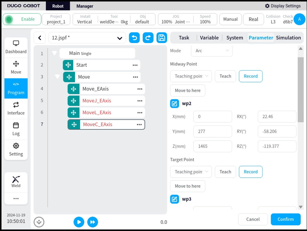
MoveC_Eaxis
External axis and robot circular motion. The robot moves according to an arc or a full circle, which can be parameterized:
Pattern: Arc or full circle
Midpoint Attitude/Midpoint 1: Can be set by way of demonstration or set as a variable, which can be changed manually after the demonstration is set.
Target Attitude/Midpoint 2: Can be set by demonstration or set as a variable, which can be changed manually after the demonstration is set.
Use parent node coordinate system: when checked, this function block uses the reference coordinate system set by the parent node Move function block, checked by default.
Reference coordinate system: when the Use parent node coordinate system is unchecked, you can set the reference coordinate system for the function block separately.
Use parent node parameters: when checked, the function block uses the end velocity and end acceleration parameters set by the parent node Move function block; when unchecked, you need to set the end velocity and end acceleration for the function block individually, default is checked.
End speed: unit mm/s, can be entered directly or by selecting a variable.
End acceleration: unit mm/s2, can be entered directly or by selecting a variable.
Fusion radius: unit mm, 0 means no fusion
Attitude control mode: If “consistent with the end point” is selected, the robot’s attitude is planned according to the end point attitude for the attitude in the circular arc path; if “consistent with the starting point” is selected, the robot’s attitude is planned according to the starting point attitude for the attitude in the circular arc path, and the attitude during the path is consistent with the starting point; if “constrained by the center of the circle” is selected, the robot’s attitude is constrained by the attitude change relative to the circular arc motion. If “consistent with start point” is selected, the robot’s pose is planned according to the start point pose, and the pose during the path is consistent with the start point; if “constrained by center of circle” is selected, the robot’s pose is constrained by the change of the pose with respect to the movement of the circular arc.
Enable OP: The OP function allows you to set the general-purpose digital output port status or operate customized events during trace execution.
OP parameter configuration is the same as Move_EAxis.
The configuration of the external axis parameters is the same as Move_EAxis and will not be repeated here.
Use of process kit model
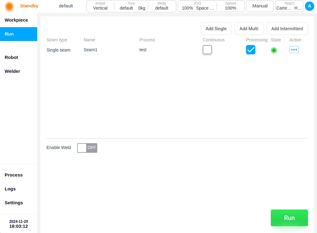
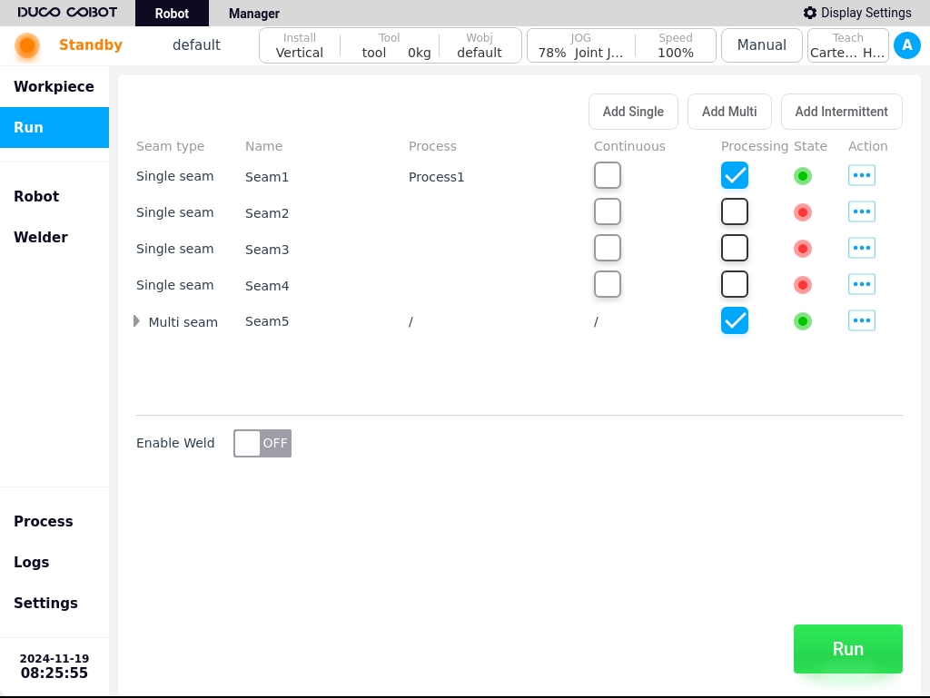
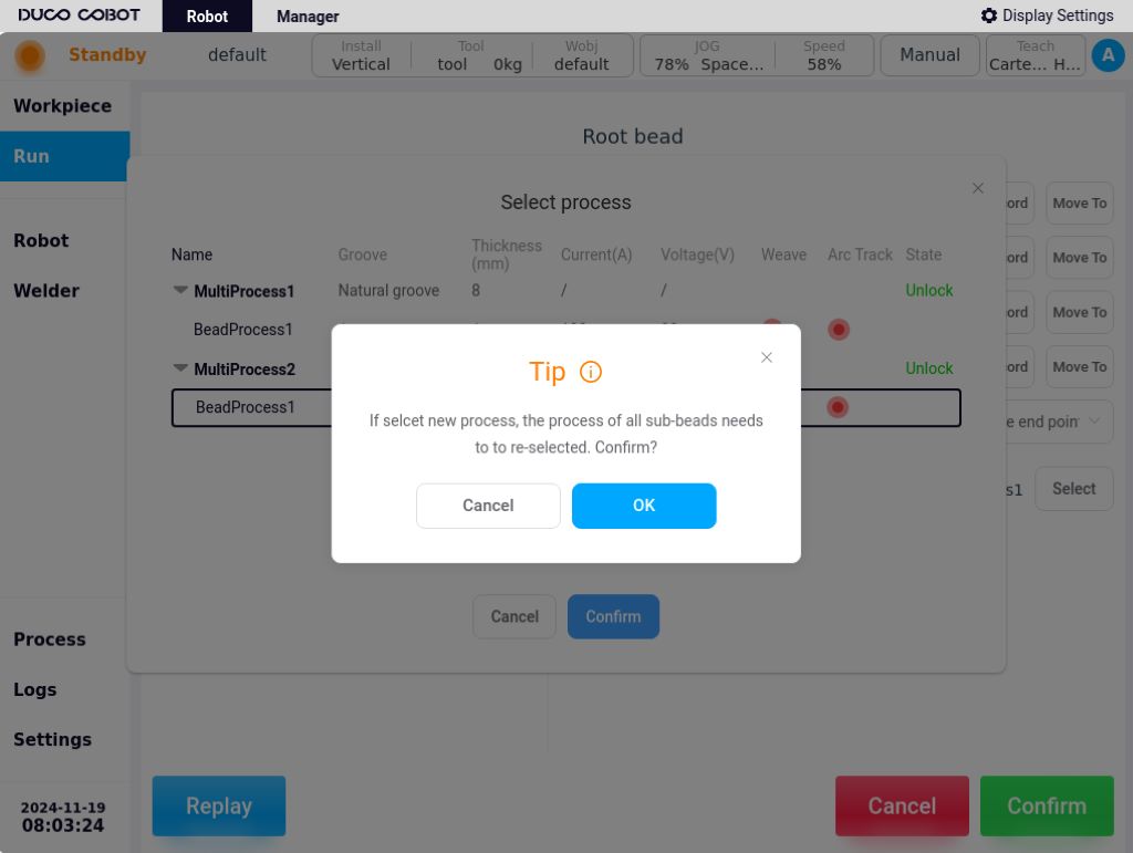
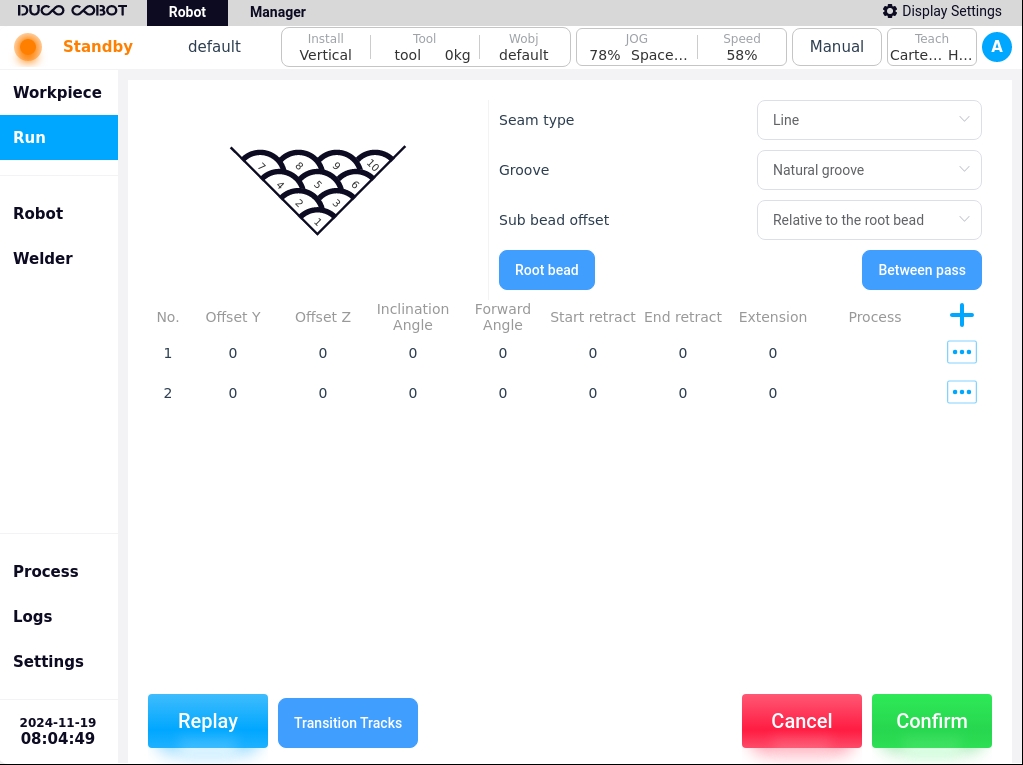
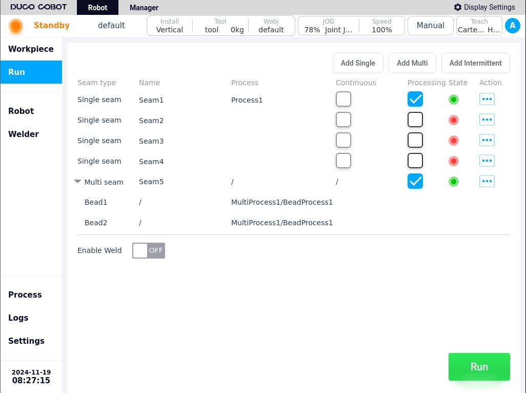
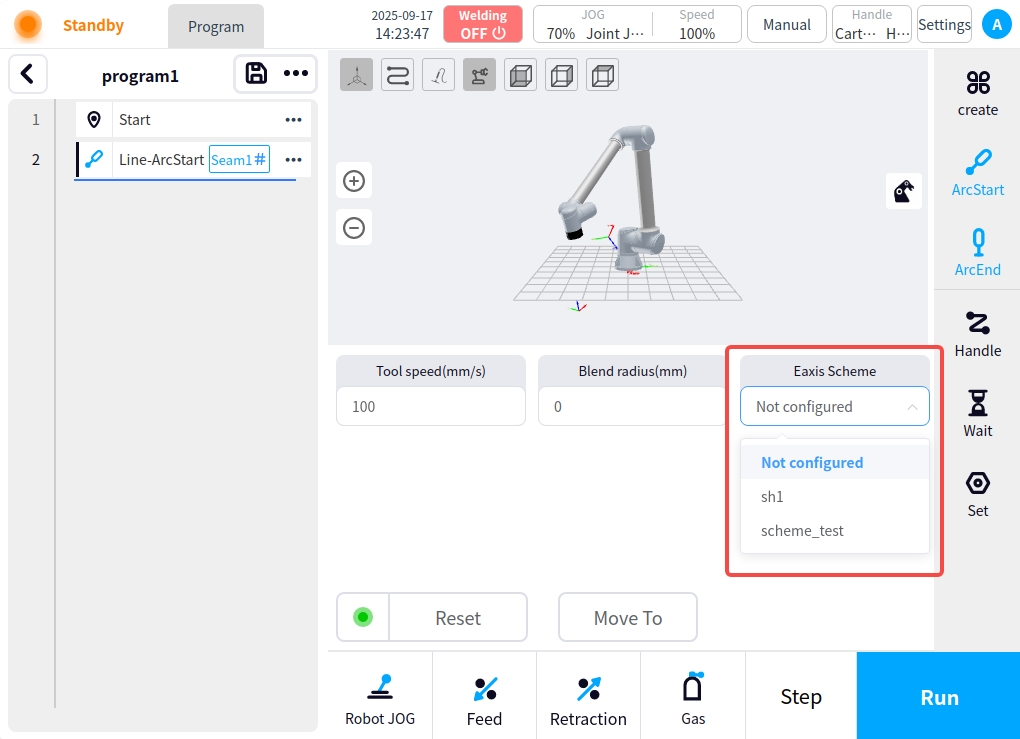
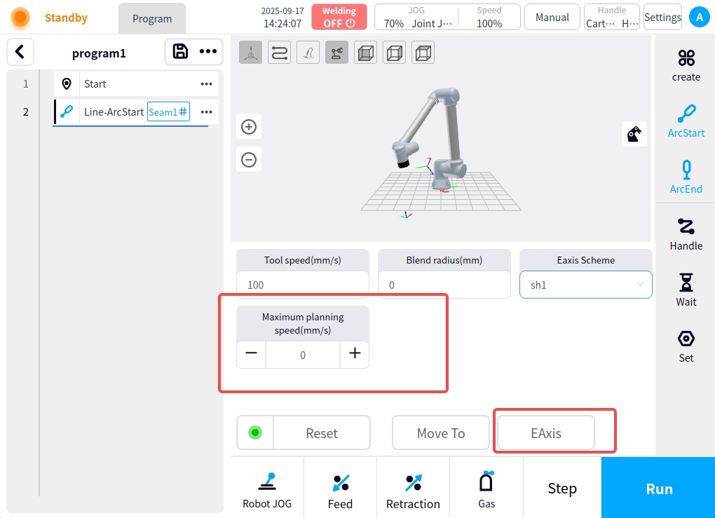
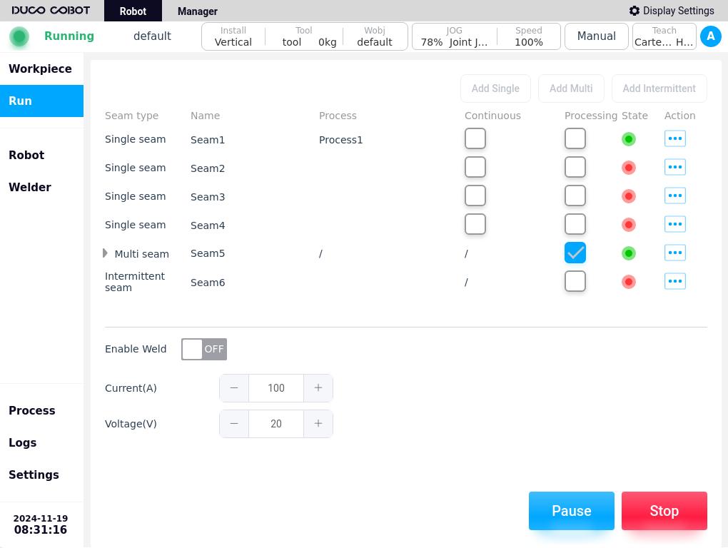
You can use the function of external axes in the welding execution page of the process package, before you use it, turn on “Enable external axes” in the External Axes Configuration - Communication Configuration.
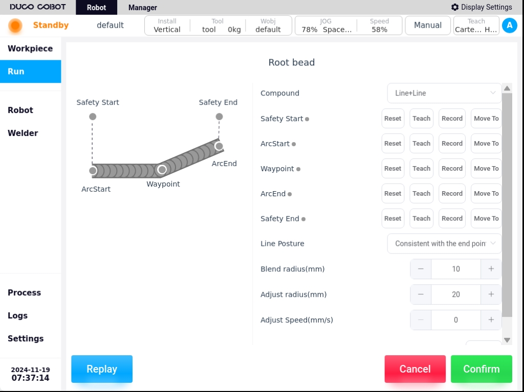
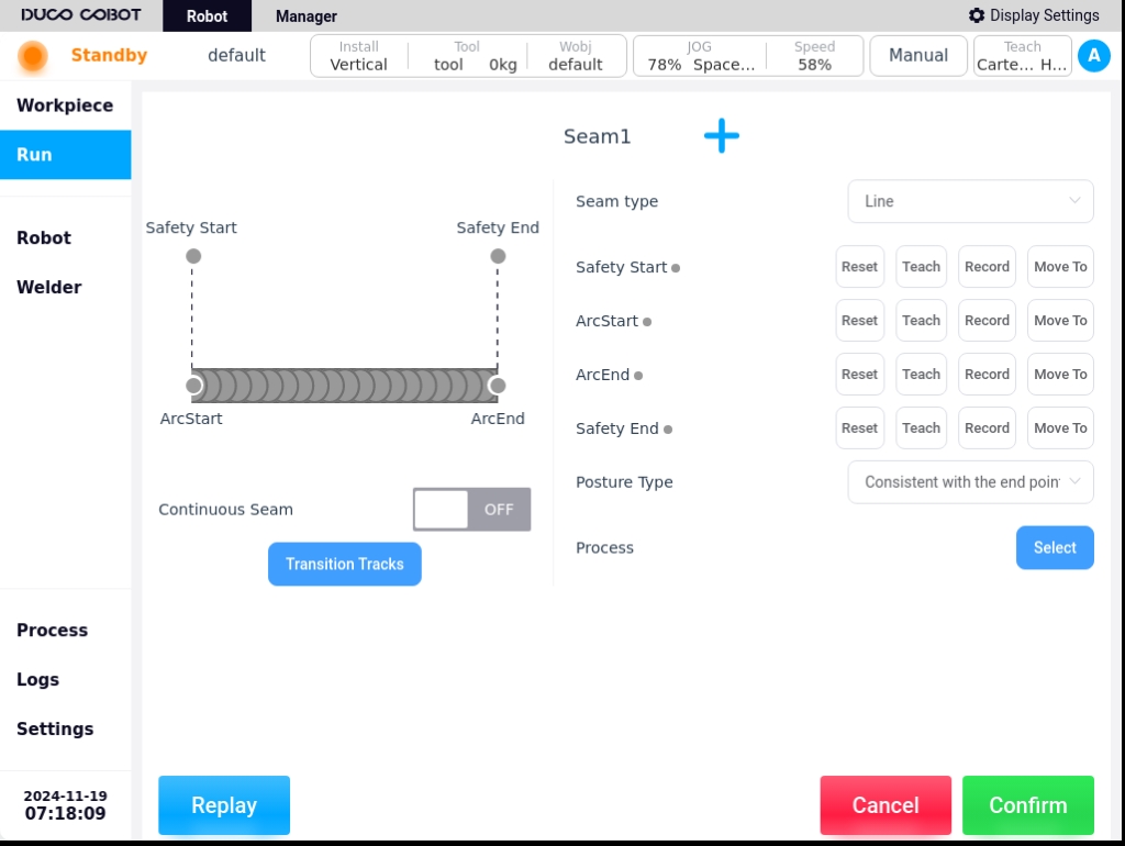
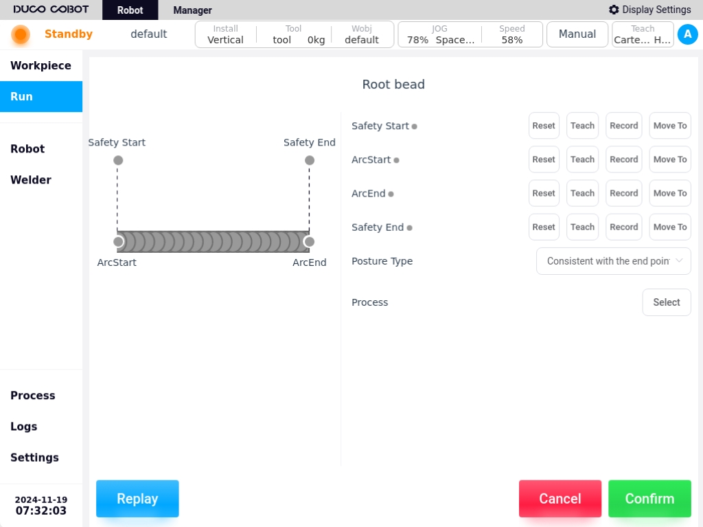
When a new weld is created on the Program Execution page, clicking on Parameter Setup allows you to configure the external axis scheme to be used for that weld, and if a scheme is selected, the maximum planning speed for the external axis. At this point, when teaching this weld point, the position information of the external axis of the selected scheme will be recorded, and clicking on the External Axis button will cause the external axis to move to the recorded target point.
Adjustment of module configuration#
Real-time adjustment of module types
Traction Module Configuration#
The traction module configurations are categorized into force-controlled traction, telemetry traction, and BW traction.
Force Control Traction#
Confirmation of Bill of Materials
No. |
Material Name |
Quantity |
|---|---|---|
1 |
Nylon Insulating Plate |
1 |
2 |
Adapter Flange Plate |
1 |
3 |
Fastening Accessories Pack |
9* |
4 |
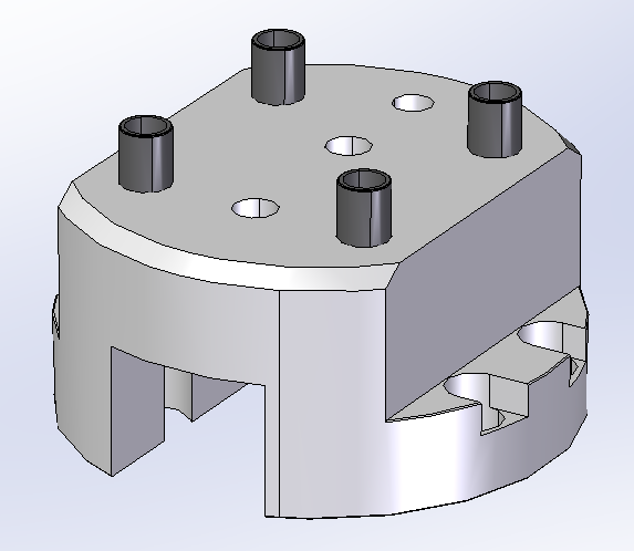
Countersunk Nut Welding Gun Bracket Assembly | 1 |
|
5 |
Force Control Traction Module |
1 |
Fastening kit: 4*M4×20 socket head cap screws + 4*M4 matching insulated screw sets + 1*φ6×20 plastic insulated pin.
Pre-installation
Remove the components mounted on the robot end;
Correctly install the force control and torch plug-in, and configure the welding working environment;
JOG Robot, so that the end of the robot is in a position for easy installation;
Robot power failure.
Installation of torch holder and adapter flange
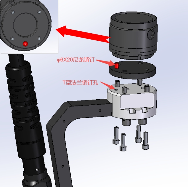
Place an M6 insulated pin sleeve in each of the 4 large holes in the T-flange;

Using a φ4X10mm pin and two M8 screw bushings, install the torch bracket on the corresponding mounting holes of the T-flange, paying attention to the tightening of the two screws, and the direction of installation of the torch bracket toward the opposite side of the eccentricity of the T-flange mounting holes.
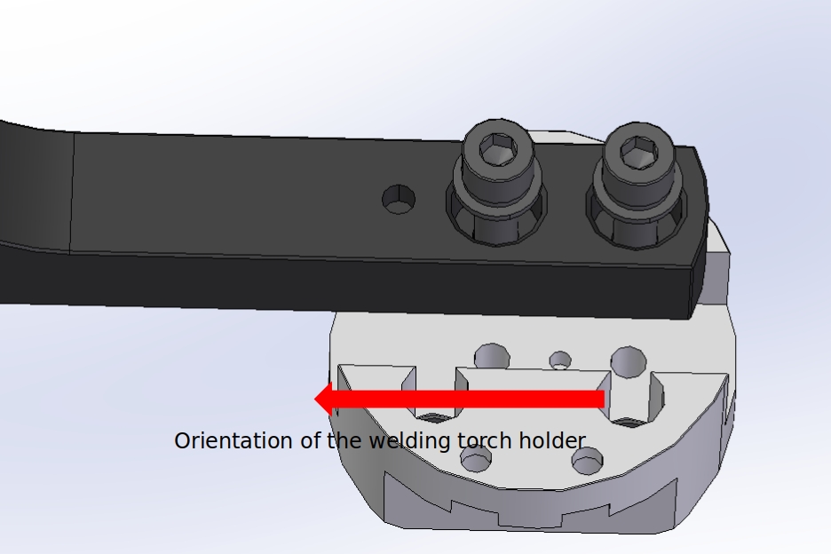
Determine the mounting direction of the torch holder according to the φ6X20 nylon insulating pin, place the end insulating plate on top of the T-flange, and use the M6×20 screw to mount the torch holder combination on the end of the robot by means of the M6 pin insulating bushing, with the linking direction as shown in the figure.

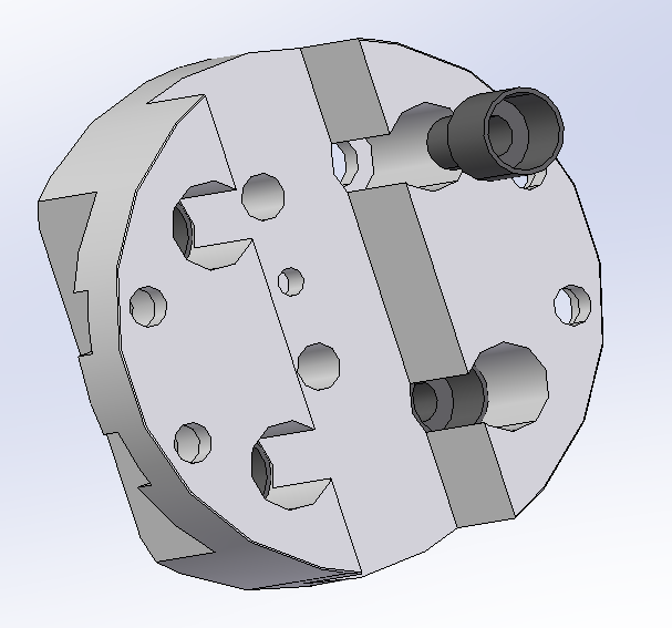
Installation of force control module
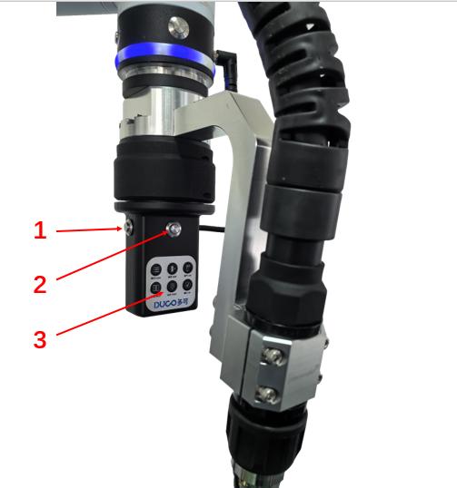
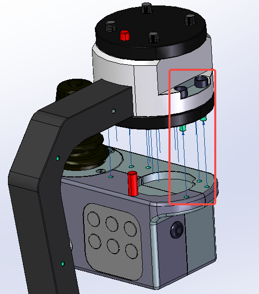
Determine the installation direction of the force control module according to the φ6X20 nylon insulating pin, and install the force control module at the lower end of the T-flange through the countersunk holes on the T-flange using four M4 bolts and matching insulating nylon bushings. The mounting direction is shown in the figure below, pay attention to adjust the mounting position so that the side of the button is facing the same direction as the deep projection of the torch bracket.
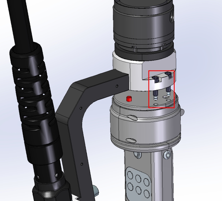
Confirm again that the robot is in the power-off state, connect the two aerial plugs (6pin and 8pin) of the force control traction module with the aerial plugs at the end of the robot, and tighten the threaded bushings on the aerial plugs respectively before powering up the robot.
Setup of robot and force control traction module
Install the Force Control plug-in (v1.3.1 or higher) and the Welding Process Package plug-in (v3.0.0 or higher).
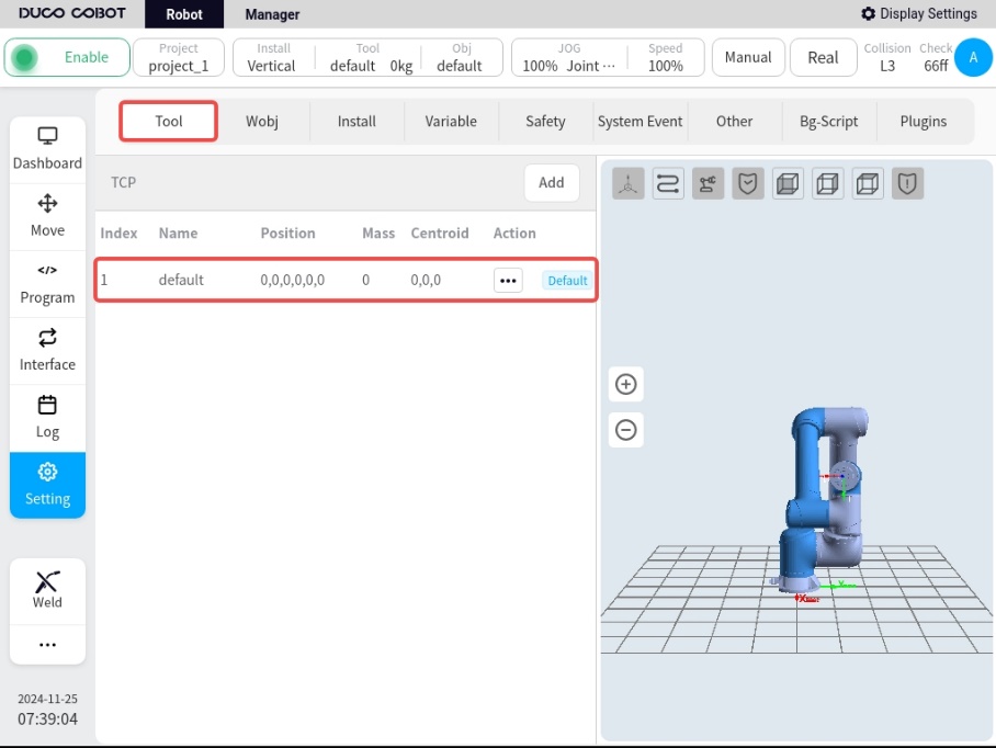
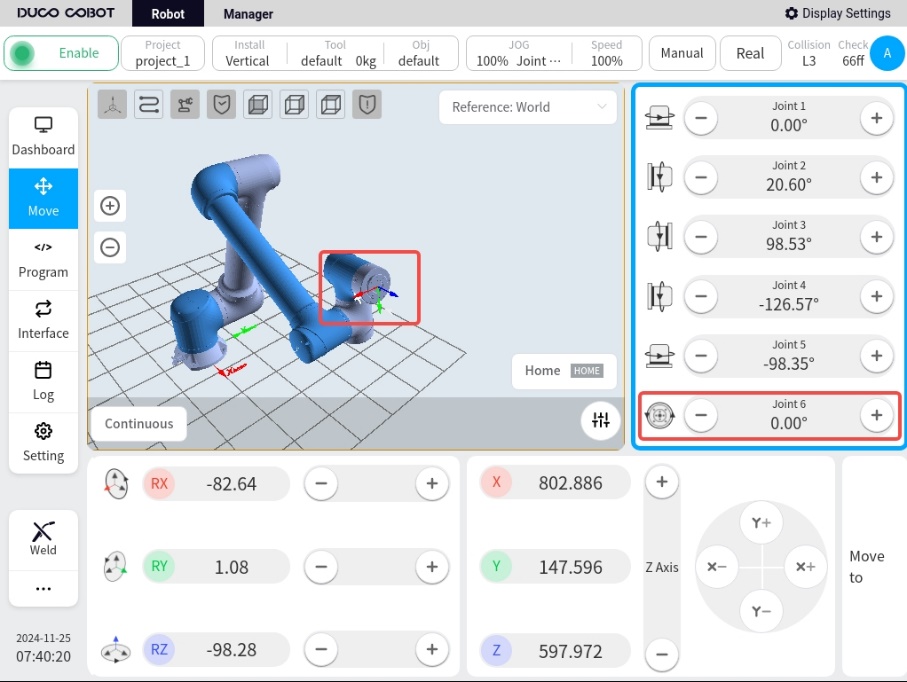
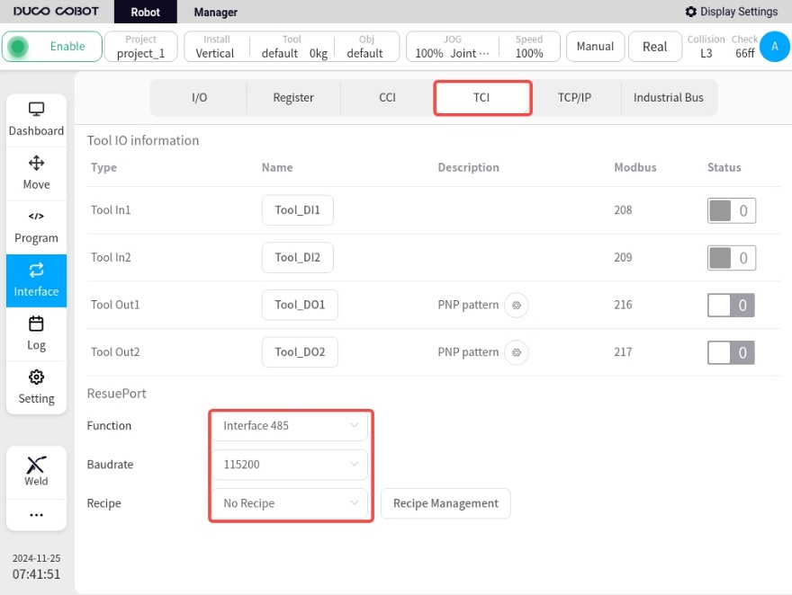
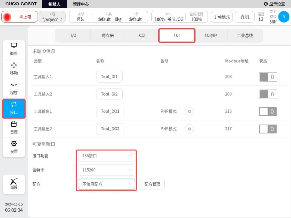
Set up in Robot Main Interface/Interface/TCI, refer to the figure below.
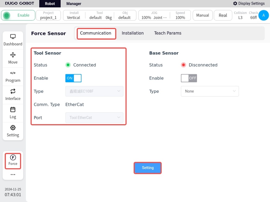
In the main interface of the robot, click the force sensor plug-in in the lower left corner to enter the force sensor configuration interface.
Enable: ON
Model selection: Xin Jing Cheng EC108F
Communication mode: EtherCat
Input port: end EtherCat port
After the setting is completed, press Set, Confirm Status, etc. to display a green light, indicating a successful connection.
In the traction interface.
Select the traction module type as Force Control Traction Module (TCS-FX620), click Setting, and the “Setting Successful” pop-up window will appear.

Under System Setup/Welder Setup, select the welder model currently connected to the robot and connect it. If the robot is not actually connected to a welder, you can select the AOTAI welder for setup, refer to the following figure for details.
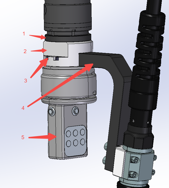
Functional description of the force-controlled traction module
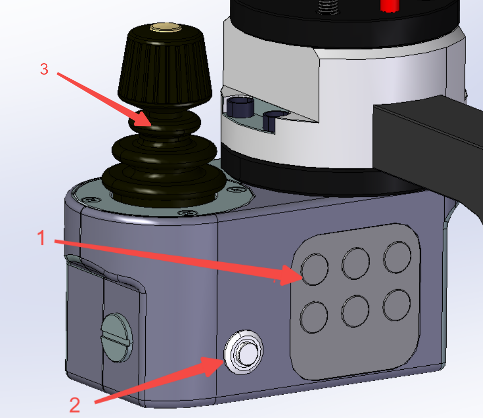
The Force Control Traction Module is used to improve the smoothness and user-friendliness of the customer’s traction teaching process with the robot. The functions of the buttons are described below:
Serial No. 1: High and low speed switching, after pressing this key (1S) during traction, high and low speed switching back and forth is carried out.
Serial No. 2: Force-controlled towing trigger button, long-press this button to start force-controlled towing towing, release the button to stop towing.
Serial No. 3: Welding function buttons, from top to bottom, from left to right, the functions are in order: mode, wire feed, gas feed, weld, spot and confirm six function buttons.
Mode: Reserved function button, not yet enabled;
Wire feed: Tap wire feed, adjust wire dry elongation
Gas Delivery: Press and hold to deliver gas, release to shut off gas for gas detection.
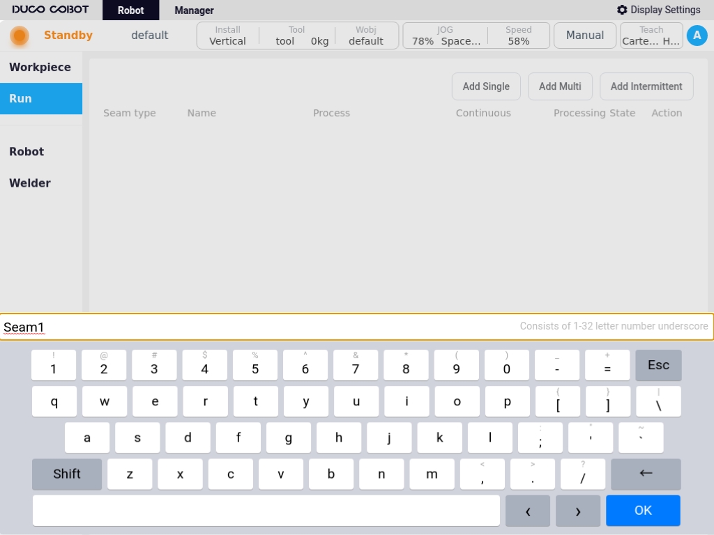
Weld Seam: Button to create a weld seam, successive keystrokes allow switching between different types of weld seams.
Points: Teach-In Points Record button, click it to record the points in sequence during the weld definition process. A long press deletes the currently recorded teach-in points.
Confirm: When the weld demonstration is complete, click this button to confirm the weld and prepare for execution.
Remote sensing configuration#
Confirmation of bill of materials
No. |
Material Name |
Quantity |
|---|---|---|
1 |
Nylon Insulating Plate |
1 |
2 |
T-type Adapter Flange |
1 |
3 |
Fastening Accessories Pack |
9* |
4 |
Welding Gun Bracket Assembly with Countersunk Nut |
1* |
5 |
Joystick Traction Module |
1 |
*Fastening kit: 4*M4×20 socket head cap screws + 4*M4 matching insulated screw sets + 1*φ6×20 plastic insulated pin.
*The torch holder assembly for countersunk nuts contains the torch.
Pre-installation
Remove the components mounted on the robot end;
Install the rocker and torch insert correctly and configure the welding working environment;
JOG Robot, so that the end of the robot is in a position for easy installation;
Robot power failure.
** Installation of torch holder and adapter flange**
Place an M6 insulated pin sleeve in each of the 4 large holes in the T-flange;

Using a φ4X10mm pin and two M8 screw bushings, install the torch holder assembly with countersunk nut on the corresponding mounting holes of the T-flange, taking care to tighten the two screws, with the direction of the torch holder mounted toward the opposite side of the eccentricity of the T-flange mounting holes.
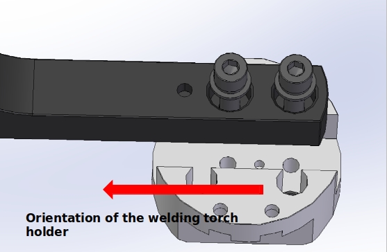
Determine the mounting direction of the torch holder according to the φ6X20 nylon insulating pin, place the end insulating plate on top of the T-flange, and use the M6×20 screw to mount the torch holder combination on the end of the robot by means of the M6 pin insulating bushing, with the linking direction as shown in the figure.
After the torch holder assembly is installed the torch TCP coordinates need to be properly calibrated according to the TCP calibration tutorial.
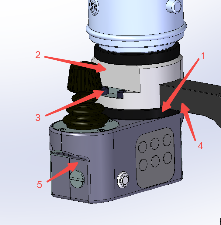
Mounting of rocker modules
Determine the installation direction of the rocker module according to the φ6X20 nylon insulating pin. Use four M4 bolts and the matching insulating nylon bushings to install the nylon insulating plate and the rocker traction module at the lower end of the T flange through the countersunk holes in the T flange; note that the nylon insulating plate is in the middle of the T flange and the traction module. Orient the mounting as shown below, ensuring that the rocker is on the left hand side when looking along the torch holder towards the end of the robot.
Confirm that the robot is in the power-off state again, connect the 8pin aerial plug wire of the rocker traction module to the aerial plug on the end of the robot, tighten the threaded sleeve on the aerial plug and then power up the robot.
Robot and rocker tractor module setup
Install the Welding Process Pack plug-in (v3.2.1 or higher).
Set up in the robot main interface/interface/TCI, refer to the figure below.
On the Traction Module Configuration screen.
Select the traction module type as ** Rocker Traction (TCS-YB620)**, click on Setup, and the “Setup Successful” prompt window will pop up.
Under System Settings/Welder Settings, select the model of the welder currently connected to the robot and make the connection. If there is no actual welder to connect, you can select the Otai welder to set up, refer to the following figure for details.
Functional description of the rocker traction module
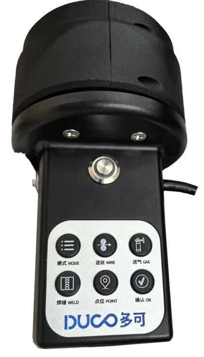
The rocker traction module is used to improve the accuracy and user-friendliness of the customer’s traction teaching process with the robot. The functions of the buttons are described below:
Serial No. 1: Towing trigger button, long press this button to start rocker towing towing, release the button to stop towing.
Serial No. 2: Welding function buttons, from top to bottom, from left to right, the functions are in order: mode (MODE), wire feed (WIRE), gas feed (GAS), weld (WELD), point (POINT) and confirm (OK) six function buttons.
Mode: Toggles the traction mode between articulating traction and Cartesian traction;
Wire feed: Tap wire feed, adjust wire dry elongation
Gas Delivery: Press and hold to deliver gas, release to shut off gas for gas detection.
Weld Seam: Button to create a weld seam, successive keystrokes allow switching between different types of weld seams.
Points: Teach-In Points Record button, click it to record the points in sequence during the weld definition process. A long press deletes the currently recorded teach-in points.
Confirm: When the weld demonstration is complete, click this button to confirm the weld and prepare for execution.

Serial number 3: operation rocker, there are three automatically reset operable axes and one push button; the operation axes control the robot’s positional attitude change in space, and the push button switches to control the robot’s movement mode. When the robot is turned on and the rocker is not used for 60s, the rocker mechanism will enter the safety lock state, which needs to be unlocked by long-pressing the traction trigger button for 3s.
The default defined movement mode at power-up is Locked Torch Attitude adjusts the spatial position of the torch at the end of the robot (Locked Attitude):
Main operating axes (X, Y angle axes): Controls the lateral movement of the welding torch in the X, Y direction.
Z operation axis (rotary axis): Controls the up and down movement of the welding torch in the Z direction.
Click the button to switch the control mode to Locked Weld Spot Adjust the torch attitude (Locked Spot):
Main operation axis (X, Y angle axis): Controls the rotation of the welding torch using the X, Y axis of the TCP coordinate system as the rotation axis.
Z operation axis (rotation axis): Controls the rotation of the torch using the Z axis of the TCP coordinate system as the rotation axis.
Clicking the button again switches the movement mode to (locked stance).
Line Laser Configuration#
The Line Laser Configuration page is used to set up the laser sensor vendor, connect the sensor, control the sensor, and calibrate the sensor. As shown in the figure, the left side area for sensor connection and operation, the right side for the calibration parameters can be viewed as well as the calibration of the laser sensor. Specific use of the laser sensor