program management#
Program List#
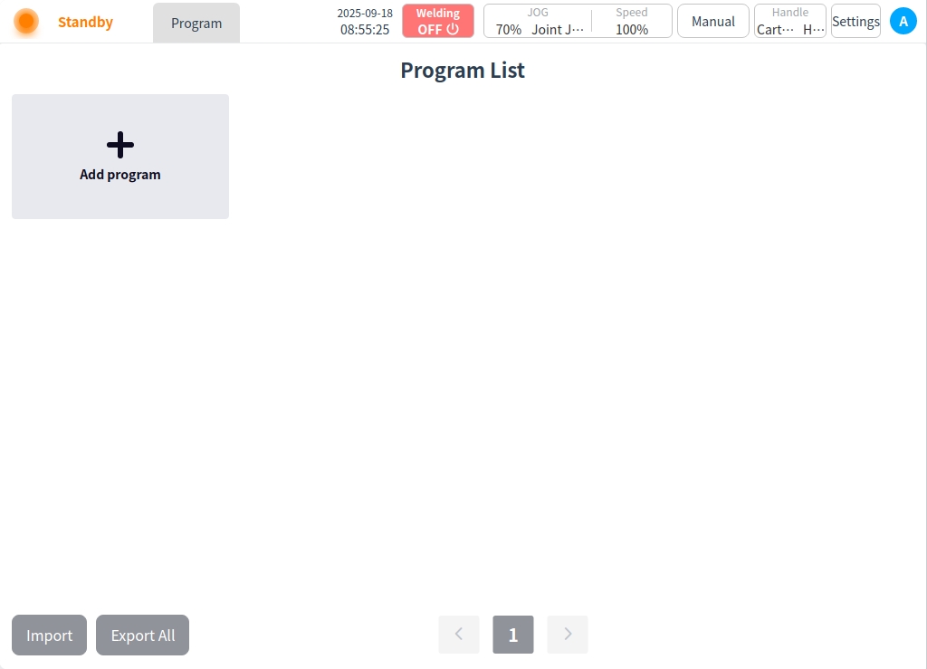
After the system configuration, you will enter the program list page, in the program list management page, you can choose to open an existing program or a new program; the first time you use it, you will enter the page of creating a new program, and the system will automatically generate the program name such as ‘Program 1’ in order, as shown in the figure below.

We will return to the New Programs page for the time being and explain it separately later. Click the Back button in the upper-left corner to return to the Program List page, which is the page you entered after clicking Open Existing Programs on the Program Management page. This screen is shown in the following figure.

Click the action icon ‘…’ of any program in the program list , the pop-up window is displayed as follows.

Program operating functions:
Open: Click “Open” to enter the program page, you can edit and run the program. You can also enter the program page by clicking the program again after selecting it.
Rename: Click “Rename” will pop up the keyboard, enter the new program name, OK can be modified.
Copy: Clicking “Copy” will bring up the keyboard and generate e.g. ‘program1_copy’, enter or modify the new program name and click ‘OK! After typing or modifying the new program name and clicking ‘OK’, you can copy the content of the current program and create a new program.
Export: Click “Export” to export the current program to a USB flash drive.
Modify Description: Clicking on “Modify Description” will bring up the keyboard to add descriptive text to the current program.
Delete: Clicking “Delete” will bring up a confirmation dialog box, and the program can be deleted after confirmation.
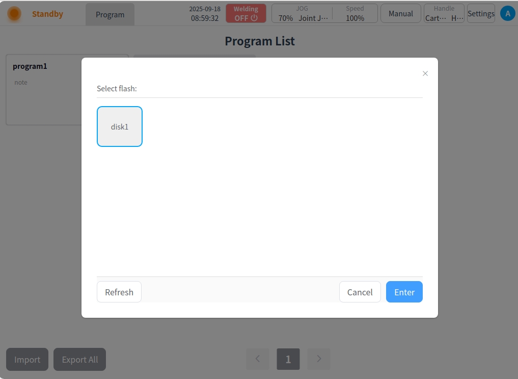
Click the “Import” button at the bottom left corner of the page to bring up a window showing the USB storage devices currently mounted on the control panel, as shown in the following figure.
Select a device and the page displays the folders and eligible files (with dwo suffix) in that device, as shown in the following figure. Select a file. Click on the “Import” button and the file will be imported into the control panel.

When importing a file and checking that the imported file is renamed with the program on the control cabinet, a rename prompt box will pop up. Click the “Change Import Name” button to bring up the keyboard and enter the new name of the artifact, e.g., enter “w1”, and the following will be displayed after successful import.

Click the “Export All” button at the bottom left corner of the page to export all the programs in the current program list to a USB flash drive;
program editor#
New or open the existing program for welding program editing, editing is completed, you can choose to save the program, or saved directly after the welding execution.
Edit Status Screen Description#
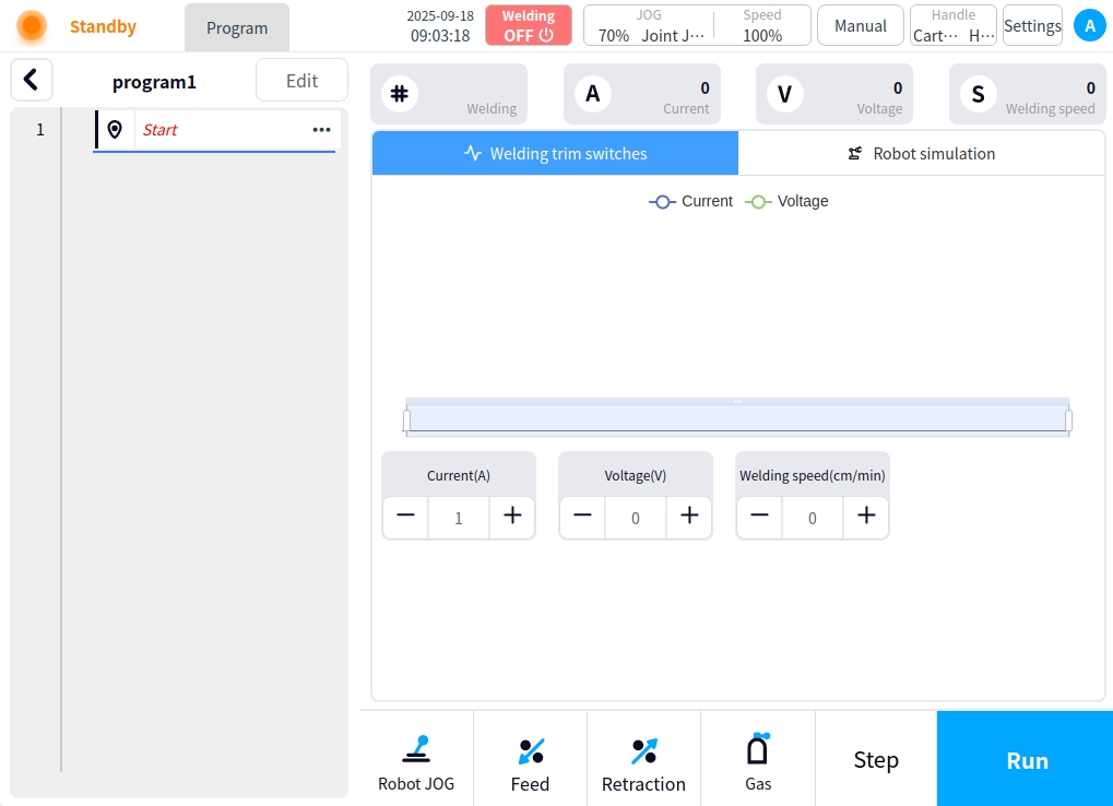
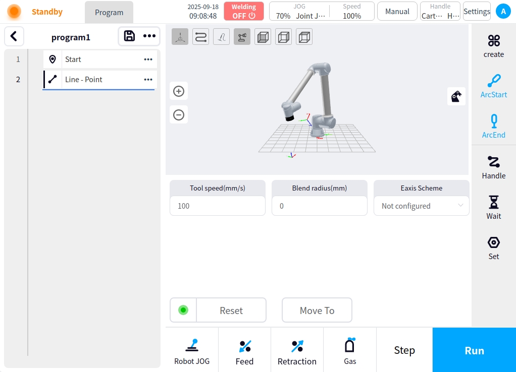
When you open the program page, the program is in the view or run state, and you cannot perform editing operations on the program in this state. Click the Edit button to enter the editing state. When you create a new program, it will enter the editing state by default. The main body of the interface is divided into several parts, the left side of the program node area, the node is added by the rightmost button, the right side of the currently selected node content editing area and command tool area, as shown in the figure below.
Node Description#
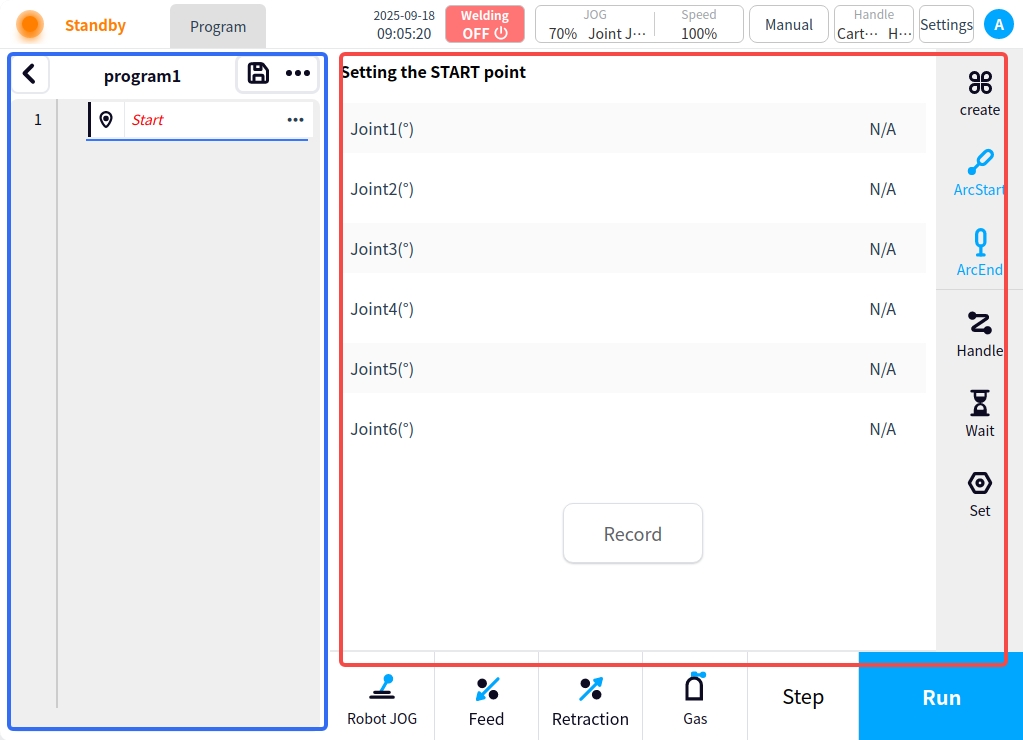
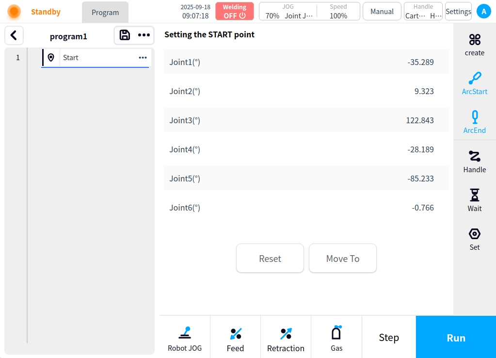
Starting point#
The start point node is the first node (robot safe attitude point) in the program, and the start point node is added by default when the program is created. Click the right content area to record the current point, you can save the start attitude point, after saving, you can reset the operation and move to the current point;
Other program nodes need to be added via the action area on the right side of the page#
Create#
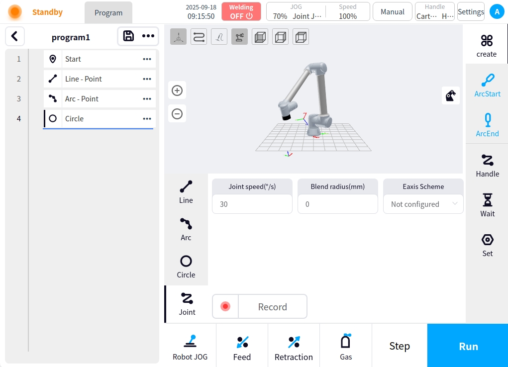
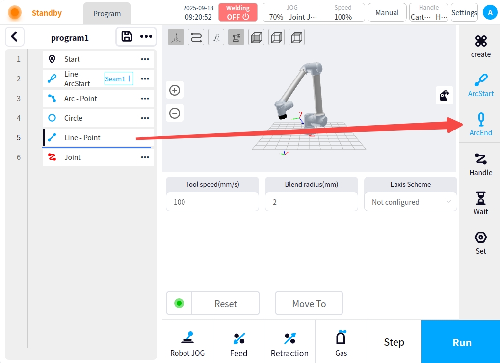
Click the Create button on the right side of the page in the operation area and the content area switches to the motion node add page. On the left side of the add page, you can select the node type to add, as shown in the figure:
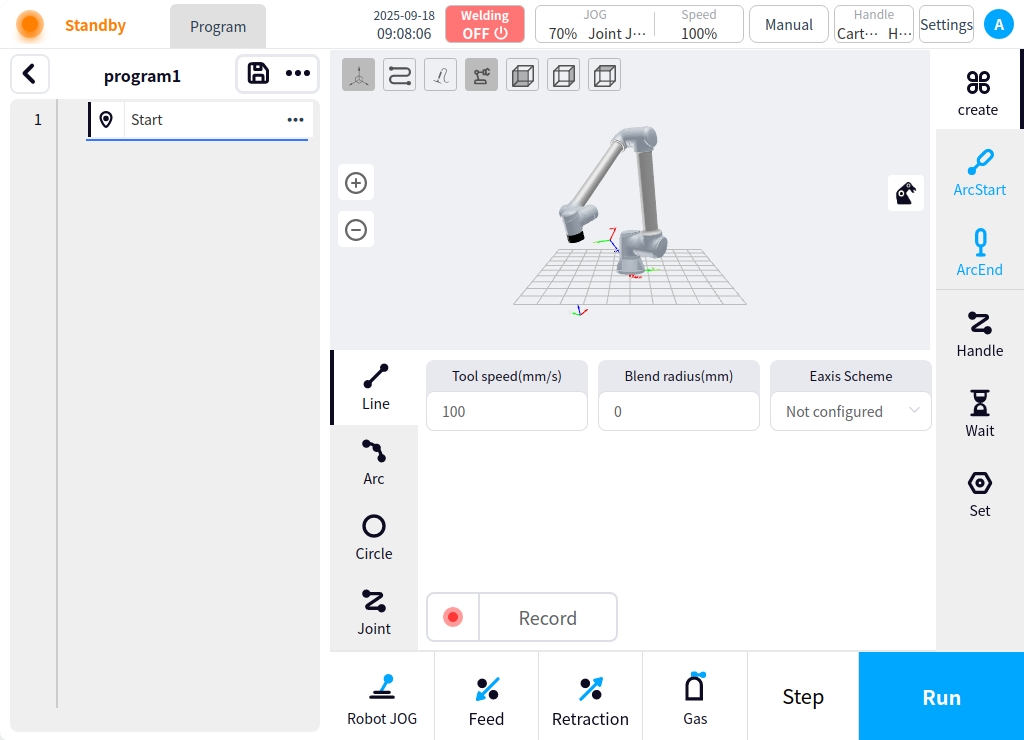
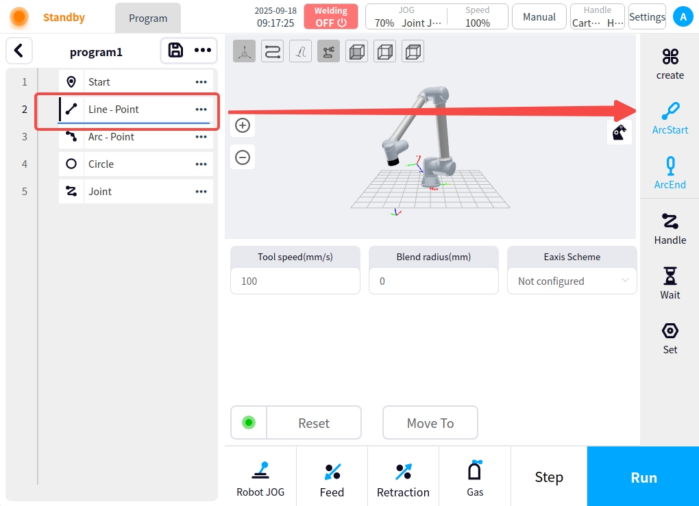
** Straight line:** Straight line node is the node for moving straight line or point in the program, after clicking straight line button on the left side, straight line-point content will be displayed in the content area, clicking Record current point button in the content area can record the current point position and add straight line-point node in the program node area on the left side. After clicking the node on the left side, you can perform reset operation and move to the current point operation; the content area can be configured for the current straight line-point with end velocity, end acceleration, fusion radius, and external axis program.
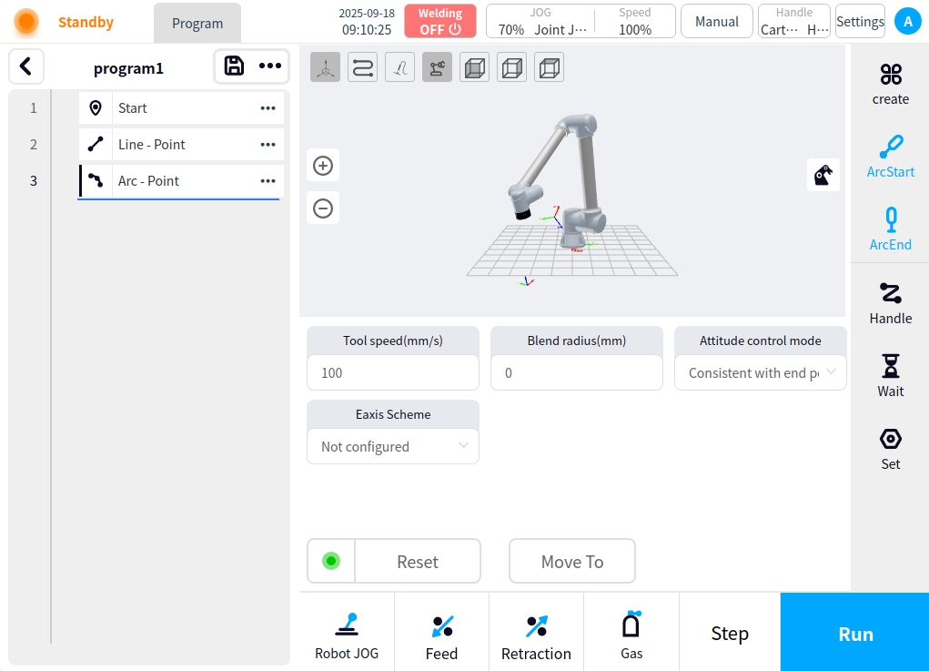
Circular Arc: Circular Arc node is the node in the program for circular motion, after clicking the left circular arc button, the content area will display the content of the circular arc, clicking the content area to record the current point button can record the current point position and add the circular arc node in the left program node area. After clicking the node on the left side, you can perform reset operation and move to the current point; the content area can be configured for the current arc with end speed, end acceleration, fusion radius, attitude control mode, and external axis program.
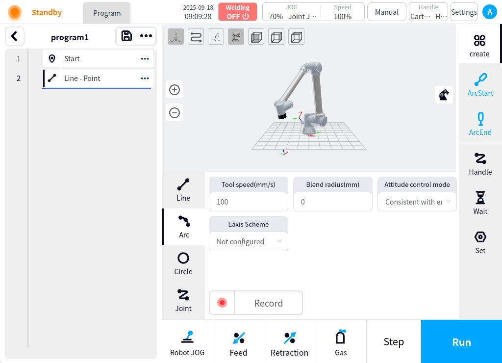
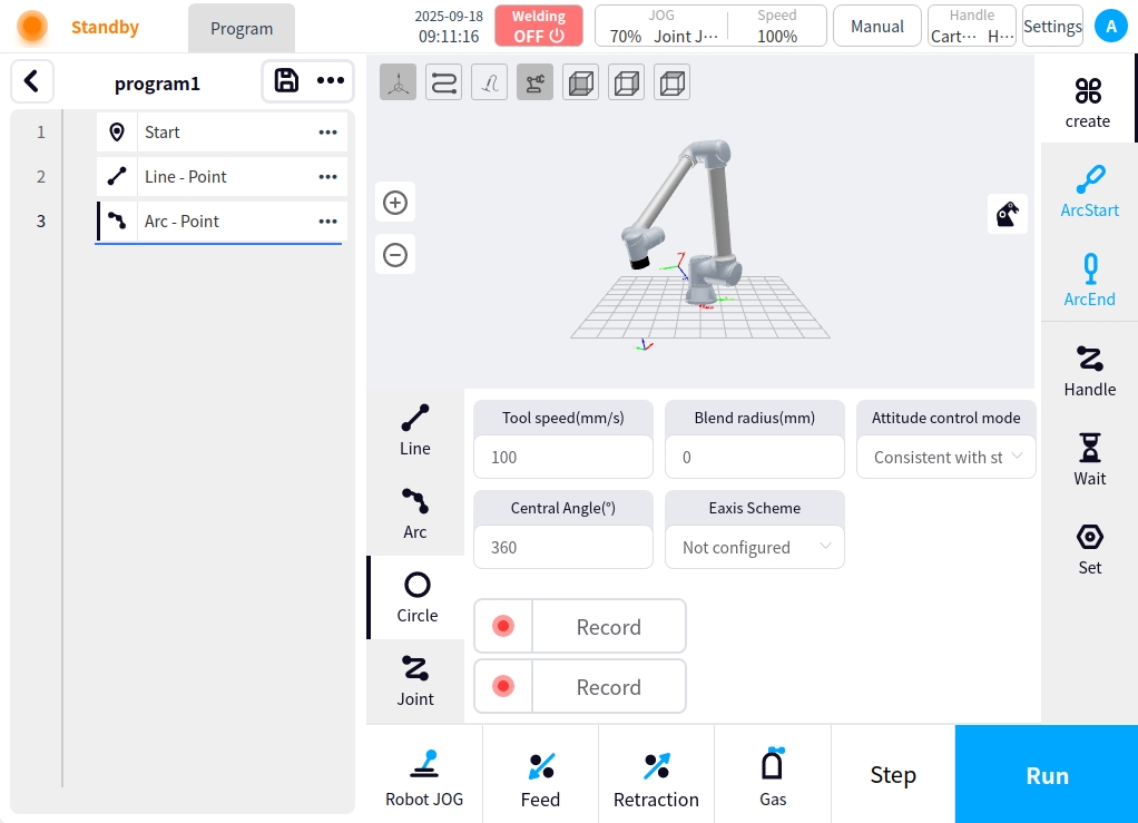
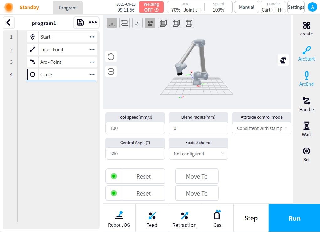
Circle: The circle node is the node for making circle movement in the program, after clicking the circle button on the left side, the circle content will be displayed in the content area, clicking the button of recording the current point in the content area can record the current point, after completing the recording of the two points, the circle node will be added in the node area of the program on the left side. After clicking the node on the left side, you can reset the operation and move to the current point; the content area can be configured for the current circle with end speed, end acceleration, fusion radius, attitude control mode, and external axis program.
Joint Motion: The joint motion node is the node of joint motion in the program. After clicking the joint motion button on the left side, the content area will display the content of the joint motion, and by clicking the button of recording the current point in the content area, the current point can be recorded and the joint motion node can be added in the node area of the program on the left side. After clicking the left node, you can perform reset operation and move to the current point; the content area can be configured for the current joint motion for end velocity, end acceleration, fusion radius, and external axis program.

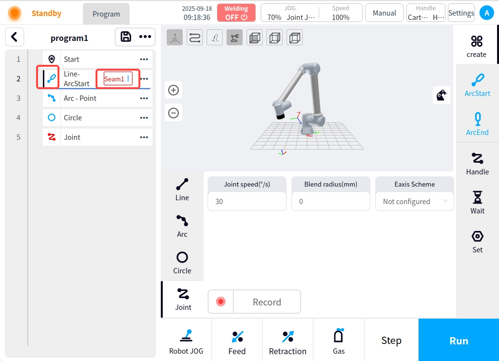
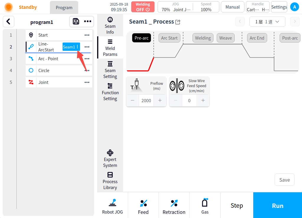
In the same time as the arc start command node, associated with its welding seam related configuration; click on the arc start node on the ‘weld’ button, you can configure the weld related process and weld settings in the content area; weld process and weld settings are described separately later; arc start node is the current arc after the execution of the weld node movement.
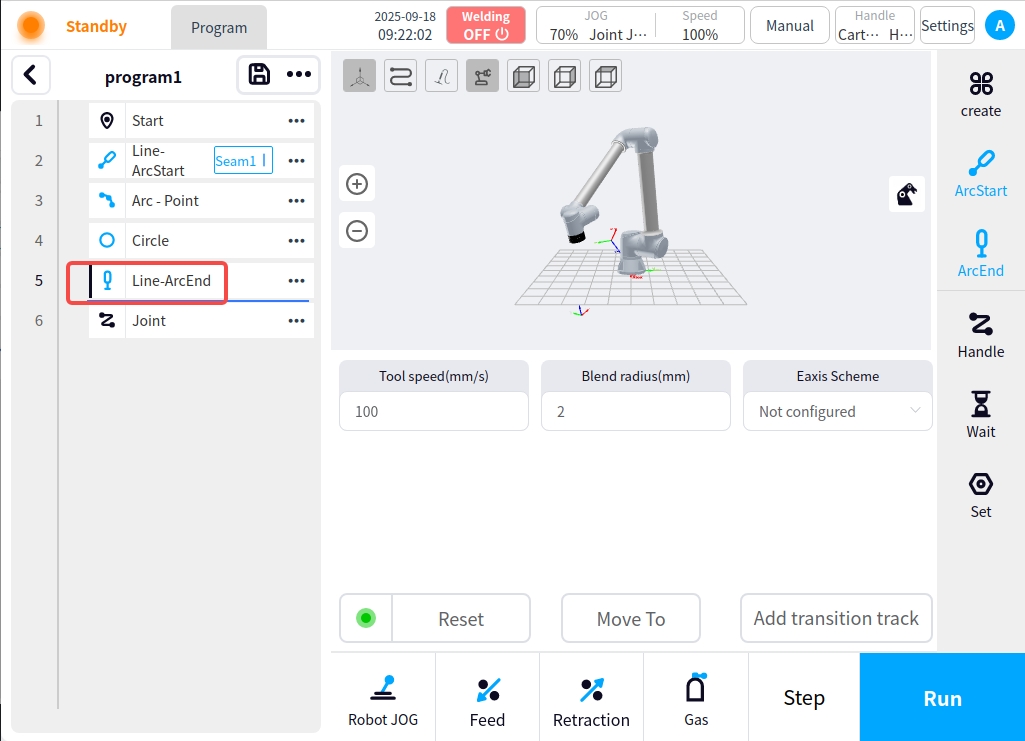
** Arc: ** Arc non-motion node, select the created motion command node (straight line node, arc node, circle node) and click on the right side of the page of the “Arc” button, you can set the node as an arc node, while the command node icon becomes an arc icon; no other configuration items, but you must add a safety point after it.
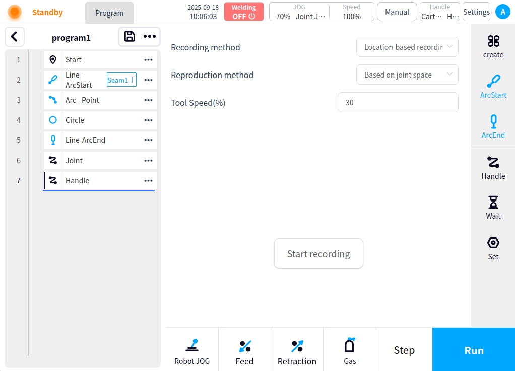
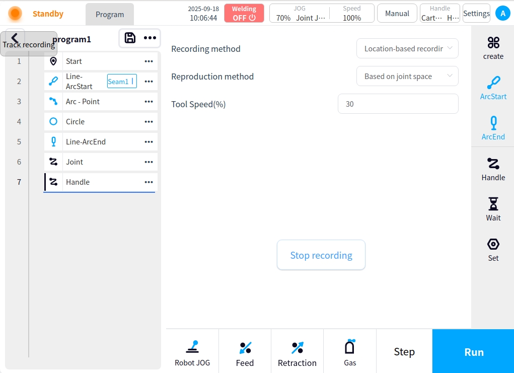
** traction trajectory:** traction trajectory node for the program for traction trajectory movement node, the right side of the content area to provide trajectory recording mode, reproduction mode, speed configuration items, configure the trajectory can be clicked on the start recording button for traction trajectory recording, the upper left corner of the interface can be seen in the trajectory recording prompts, click on the button to stop the record record is complete. And add the traction track movement node in the left program node area.
Node Related Operations#
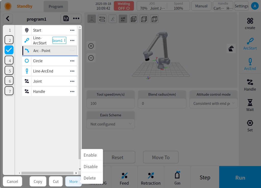
Clicking on the  of a node brings up the node’s related actions popup, as shown in the following figure.
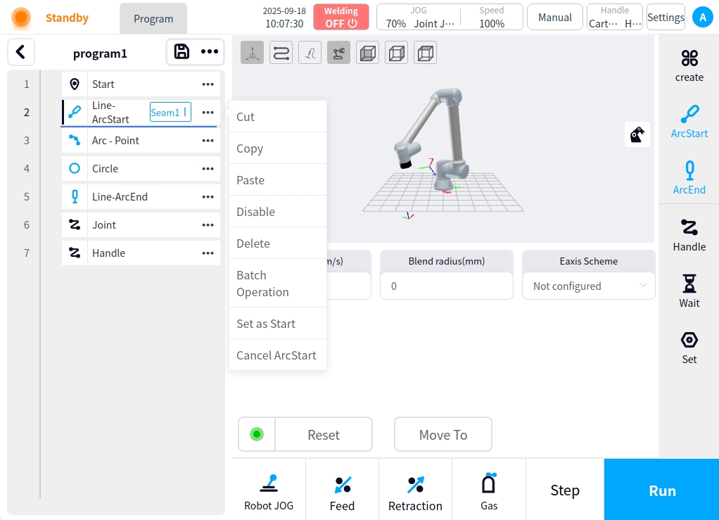
The operation is as follows:
Cut: After cutting the current command, click
in the other command node to check Paste to add the cut command below it;Copy: After copying the current command, click
in the other command node to check Paste to add the cut command below it;Paste: After cutting or copying other commands, click
in the current command node to check Paste and add the cut or copied command below;Not enabled: When set not enabled, the program node will be grayed out and the program will not execute the current node;
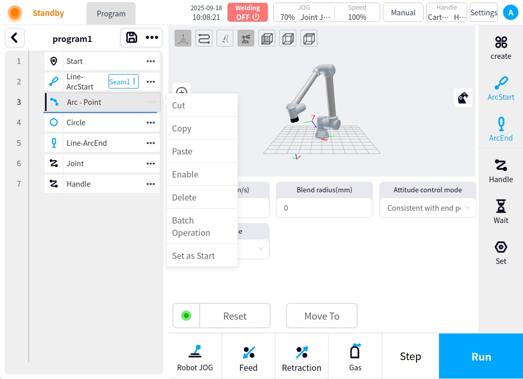
Enable: Enables program nodes that are set to be inactive;
Delete: Delete the current instruction;
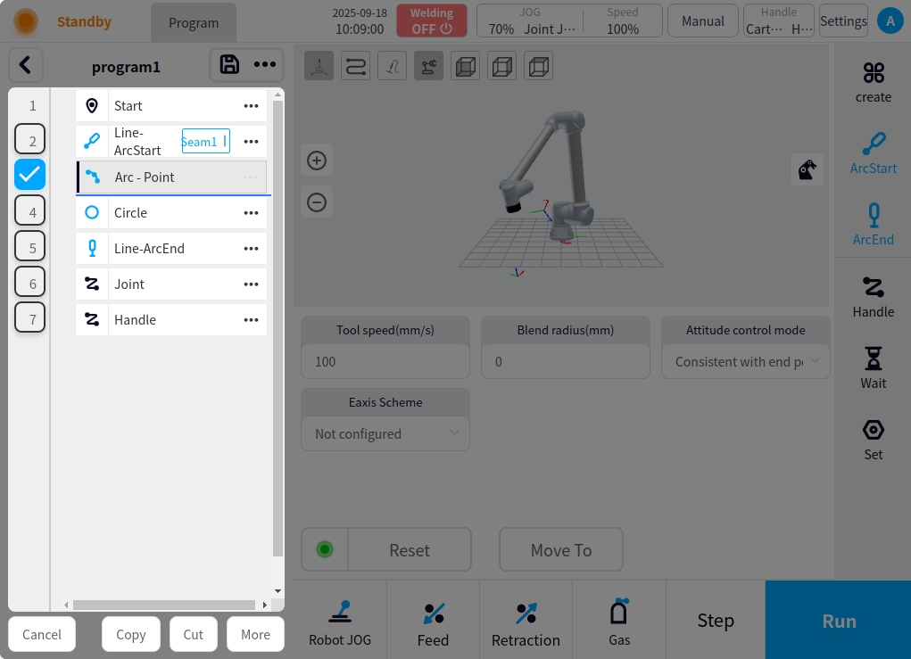
Batch Operation: Batch operation can be performed on Cut, Copy, Paste, Delete, Disable, Enable and other commands after clicking the Batch Operation button; operation target selection is performed through the check box on the left side of the program node.
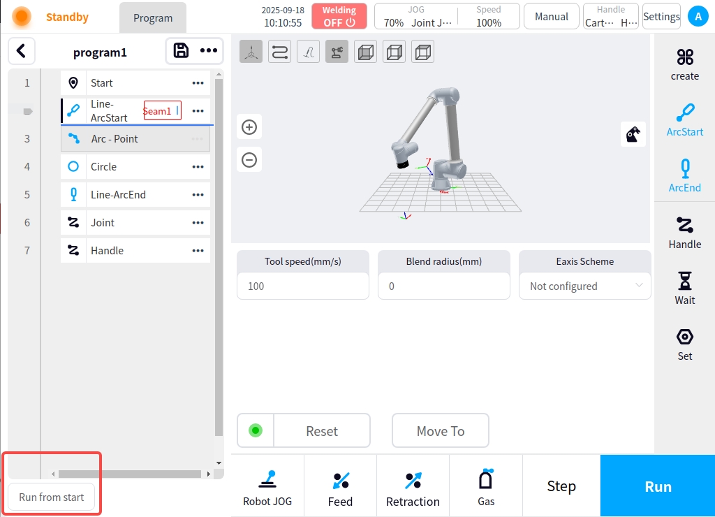
Set as start line: Set the current instruction as the start line of the program run; after setting as start, a
icon is displayed on the left side of the instruction node, indicating that the current instruction is the start, and the ‘Cancel start line’ button appears at the bottom. Clicking the ‘Cancel Start Line’ button will cancel the start line marker.
Caution
The Start Point node only supports paste operations.
Welding process and setup#
The weld at the starting node of the program is set up with the parameters of the process. Including seam information, welding parameters, weld channel settings, function settings, expert system, process library. Among them, weld information, welding parameters, weld channel settings, expert system several items are not introduced, please refer to the process library section part of the description.
Process library selection#
Click the Process Library button on the left to enter the process library selection interface. After selecting the corresponding process, click the Save button at the lower right corner to get the corresponding process data. And jump to the welding channel setting page.
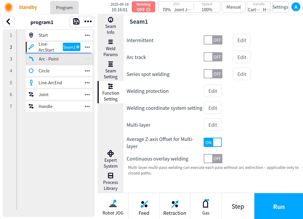
Function Setting#
Click the Function Setting button to enter the Function Setting page, which provides Intermittent Welding, Arc Tracking, Continuous Spot Welding, Weld Protection, Weld Path Coordinate System Setting, Multi-Layer Multi-Pass Setting, Multi-Layer Multi-Pass Offset Z-Direction Averaging, and Continuous Stack Welding;
intermittent soldering#
Click the Edit button after intermittent welding to enter the intermittent welding parameter configuration page, which automatically modifies the interval length and prioritizes the guarantee of welding length in case of insufficient welding workpiece length.
Intermittent Weld Enable Button: used to enable or disable intermittent welding;
Weld length: the length of the weld at one end of the intermittent weld;
Interval length: the length of the weld interval between the two ends of the intermittent welding;

arc tracking#
Click the Edit button after arc tracking to enter the arc tracking parameter configuration page, turn on the arc tracking switch to see the arc tracking corresponding parameters.
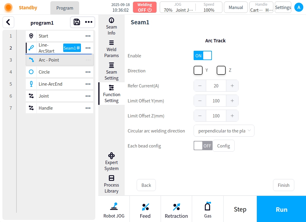
Arc Tracking Enable Button: used to enable or disable arc tracking;
Compensation direction: set the compensation direction of arc tracking, optional Y direction or Z direction, i.e. left-right direction or up-down direction;
Reference current (A): arc tracking reference current data value, unit A, default value is 20;
Maximum compensation distance limit Y (mm): maximum compensation distance value in Y direction, unit mm, default value 100;
Maximum compensation distance limit Z (mm): maximum compensation distance value in Z direction, unit mm, default value 100;
Circular welding direction: optionally perpendicular to or parallel to the circular plane;
Individual configuration for each weld pass: individually specify whether to enable arc tracking mode and reference voltage for a certain weld pass single, e.g.: set the first pass to enable arc tracking mode;
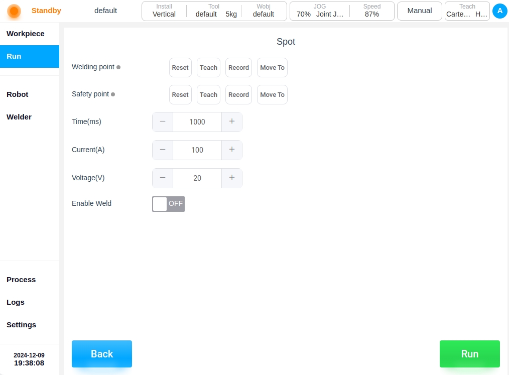
Continuous spot welding#
Continuous spot welding is performed in a section of the weld according to the set welding time and interruption time.

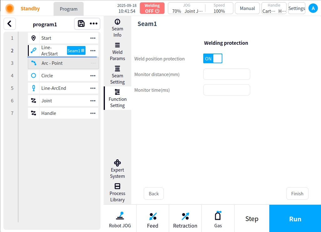
Welding protection#
Click on the Edit button after Weld Protection to enter the Weld Protection Settings page. The principle of the protection function during welding is to monitor in real time whether the end of the robot tool has a displacement amount that exceeds the monitored displacement. If the end of the robot tool does not produce enough displacement within the set monitoring time, it is judged that the robot is in the same position, at which time it will trigger the welder to close the arc command. The purpose of this function is to prevent the robot from having a long welding operation in the same position, in order to prevent the weldment from burning through.
Welding protection enable button: for whether to enable welding protection;
Monitor Displacement: set the displacement value for monitoring displacement, in mm;
Monitoring time: the set monitoring time, unit ms;
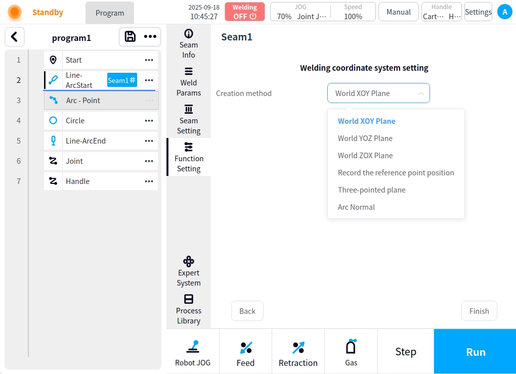
Welding channel coordinate system setting#
Click the Edit button after setting the weld channel coordinate system to enter the weld channel coordinate system setting page. You can set the weld pass coordinate system creation method; Weld pass coordinate system creation method: optional world XOY plane, world XOZ plane, world YOZ plane, record reference point position attitude, three-point plane method, arc plane normal; Which the world XOY plane, the world XOZ plane, the world YOZ plane can be directly selected;
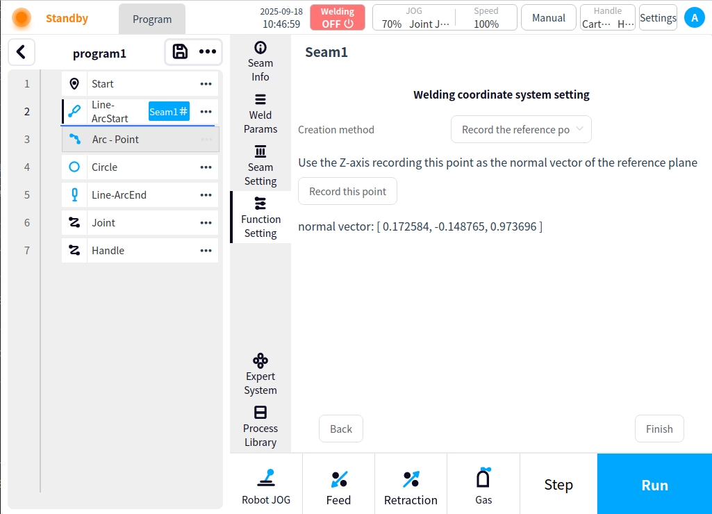
Record reference point position: Record reference point position When selected, the desired reference point position needs to be recorded. As shown in the figure, the coordinates will be displayed after recording;
Three-point plane method: Teach three points and use the plane composed of these three points as the xoy plane of the weld channel coordinate system; click on the Calculate button after teaching three points and the corresponding coordinate system will be calculated;

Normal direction of arc plane: If the weld trajectory is a circular arc, the normal direction of the arc plane will be used as the normal direction of the weld channel coordinate system;

multilayer and multichannel#
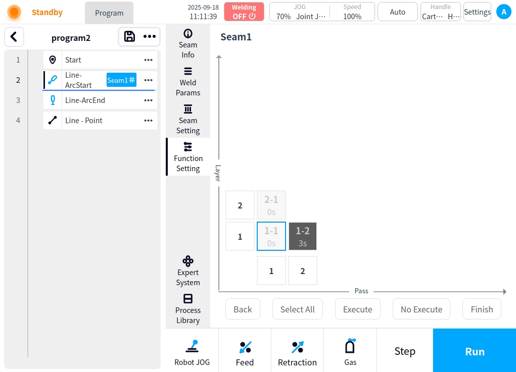
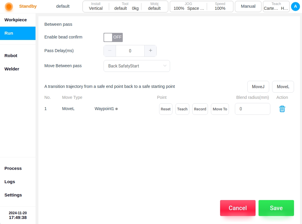
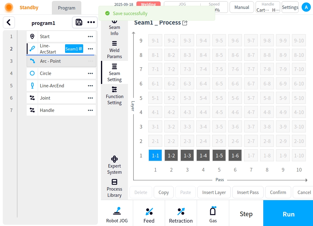
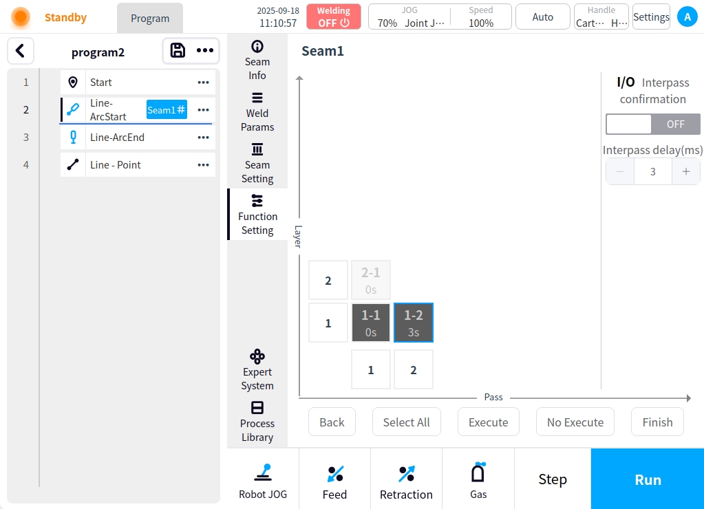
Click the Edit button after multi-layer multi-pass to enter the multi-layer multi-pass page. If there is no process setup, click on the page to open the weld channel data is empty; if you have set up the multi-layer multi-pass process data, it will generate the corresponding weld channel to enter the page as shown in the figure below:
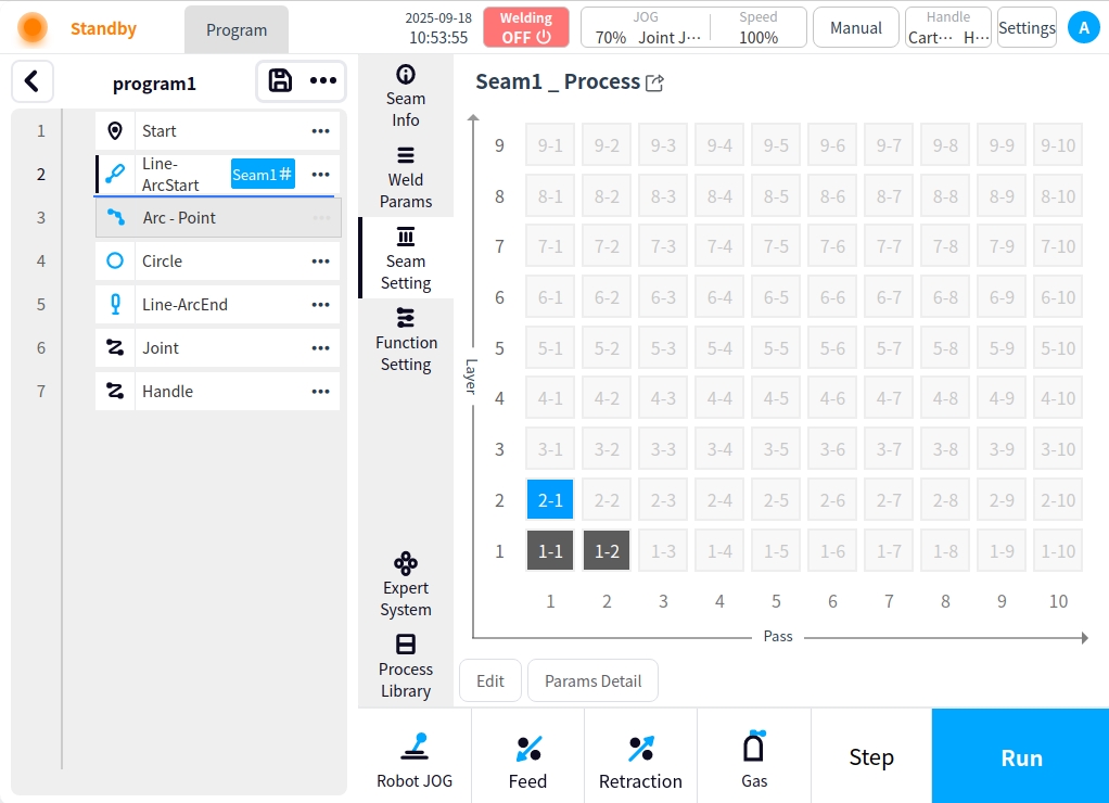
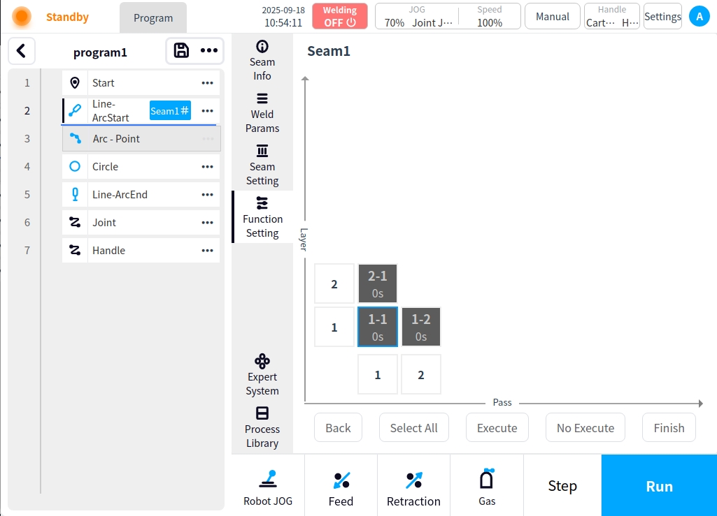
Functions: Performs multi-layer, multi-pass welding, with the ability to set the pass delay and configure inter-pass confirmation, as well as perform any operation for one or more passes;
Operation:
The blue border indicates the selected weld path; the dark gray block indicates the executable weld path; the light color block indicates the non-executable weld path;
Bottom buttons: Select All means all weld passes are selected; Execute means the selected passes are set as executable; Not Execute means the selected passes are set as non-executable;
Clicking on an individual weld pass block does the following: the first click selects and the second repeat click sets it to executable/non-executable;
Click on the bottom of the horizontal numbers block can be carried out as follows: the first click selected the entire column , the second repeat click can be set to the current column executable/non-executable, take the current front column from the bottom to the top of the first weld line block status value as a reference to set the entire column of the opposite state; for example: click on the numbers of 1 column, and the first column of 1 column of the first weld line block status is executable, and the first column of the first weld line block status is executable. For example, if you click on a number in column 1 and the first weld line in column 1 is executable, clicking on the number in column 1 again will set the whole weld line to non-executable, and vice versa.
Clicking on the left vertical block of numbers does the same thing as above, but for the whole row;
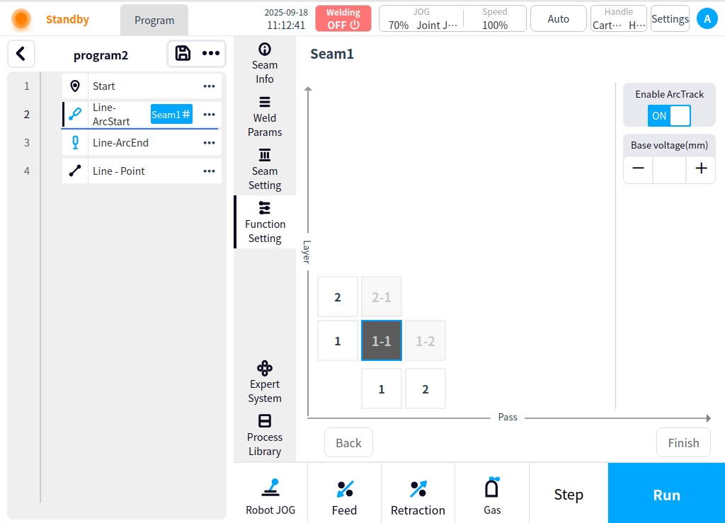
When the selected channel block is executable, the channel setting will appear on the right side of the page, which can be used for I/O channel confirmation, channel delay setting, and either one or the other. When single-selected, it is single-channel operation, and the modified value will be directly fed back to the weld channel block display; when whole row, whole column, and all-selected operation is performed, you need to click save after modifying the value to batch modify and display it in the weld channel block; the following figure is shown:
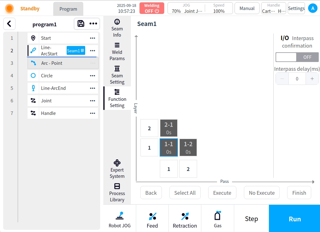
Once the settings are complete, save with the Done button at the bottom right;
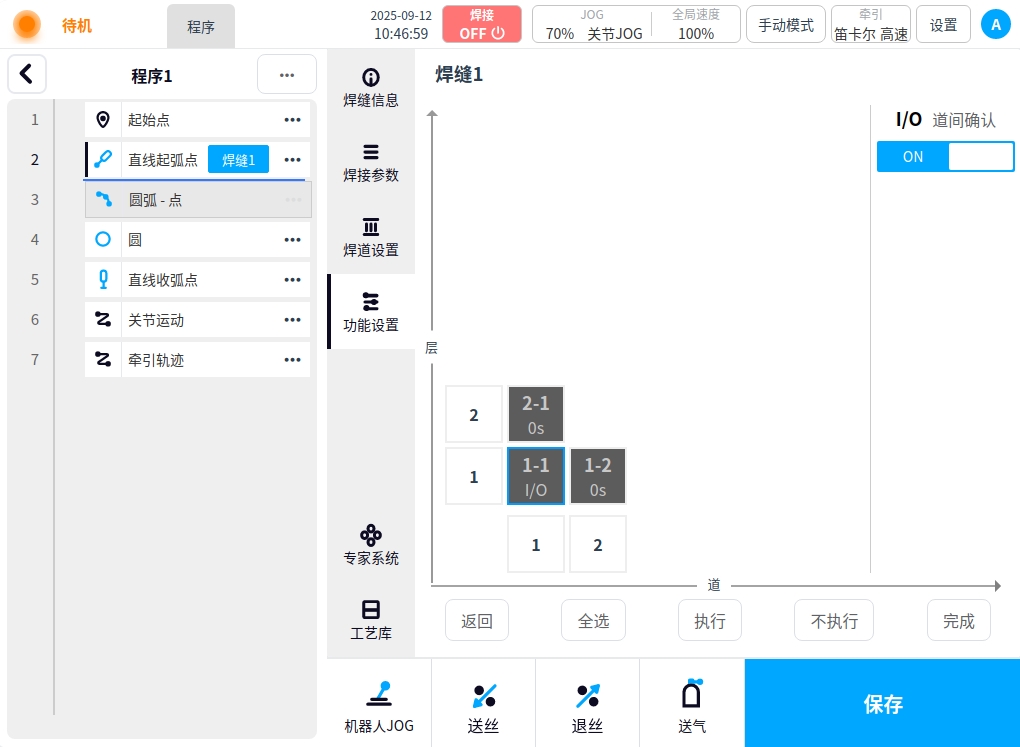
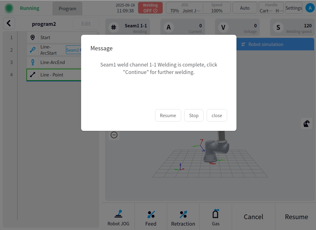
I/O inter-channel confirmation: After the weld channel is opened for inter-channel confirmation, the inter-channel confirmation prompt box will pop up before the welding execution of the current weld channel, and the welding will be carried out after clicking Continue to run;
** Inter-channel delay:** After setting the inter-channel delay for a weld channel, the welding will continue to weld after a delay of the set time before the execution of the current weld channel, e.g., the following figure: Setting a delay of 3 seconds, the welding will continue to weld after a delay of 3 seconds before the execution of the current weld channel;
Any weld path execution: Select the weld path that needs to be executed and switch to the executable state, click the Finish button at the bottom right to save it; return to the program execution page to execute the program, and the running weld path will be the set weld path. For example: Execute all weld passes of the second layer only.