


mechanical person#
Click on the robot to go to the robot configuration page, which contains the robot’s installation method and TCP calibration;
1.Installation#
The robot configuration page defaults to the installation direction configuration, you can choose the vertical, horizontal, inverted or customized way; after selecting, click Settings to save;

2.TCP calibration#
The TCP Calibration sub-page displays a list of system tools TCP, the list contains the tool name, position coordinate system information, mass, center of mass, and operation items. The following figure shows the list.

additional#
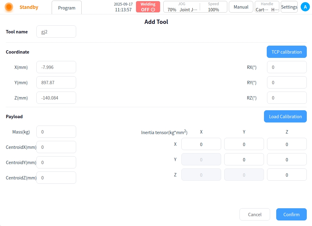
Click the Add button in the upper right corner of the list to enter the Add Tool page, where you can set the tool name, coordinate system information, and load information settings.

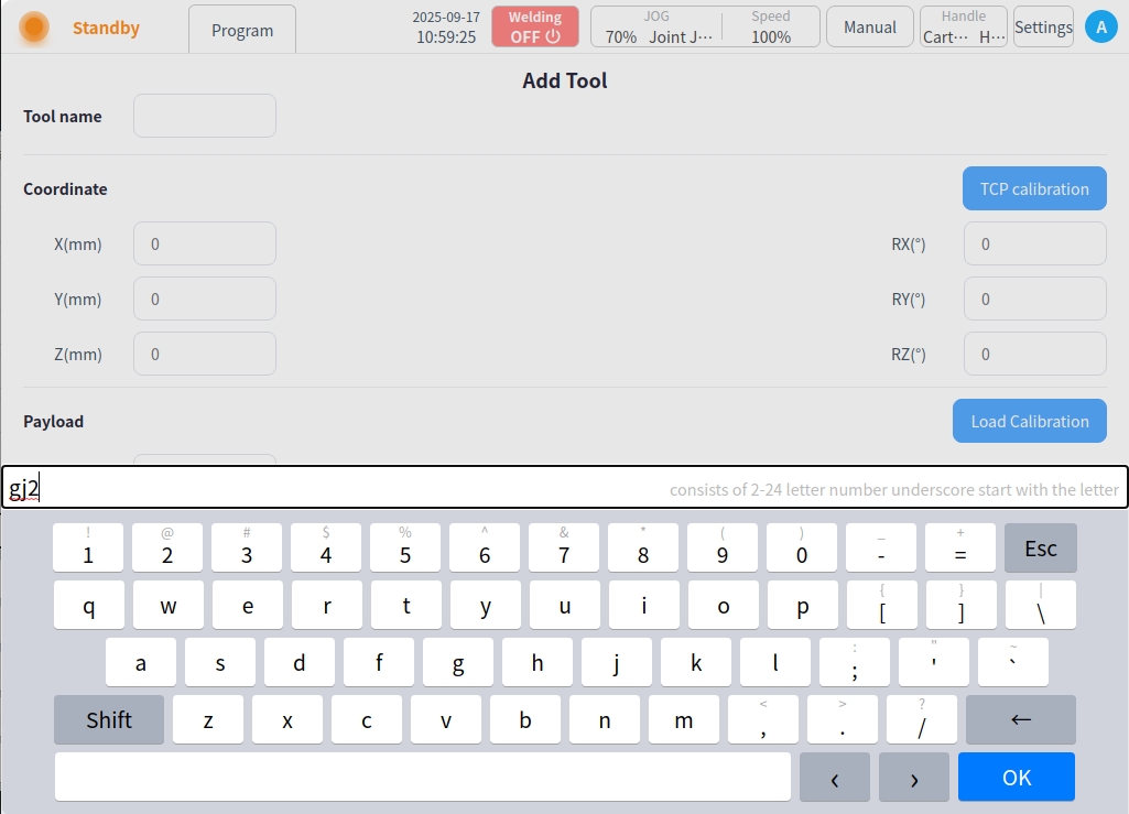
Name of tool
Click the tool name input box to bring up the keyboard input box, enter the tool name, such as “gj2”, click ‘OK’ to save.
Coordinate system information
Tool coordinate information can be obtained by manual input or TCP calibration. For manual input, you can directly input the corresponding coordinate information in the input box. If you need TCP calibration, click the “TCP Calibration” button on the right side to enter the TCP calibration process as shown in the following figure.
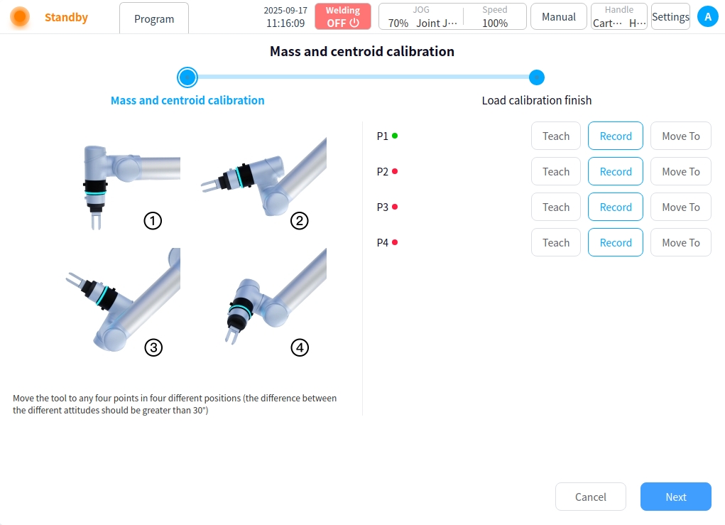
First of all, it is necessary to fit the tool points to the calibration pin fixing points, i.e., teach the points P1-P4, in different attitudes, and it is recommended that the attitude angle change between points is between 45° and 90°. This is conducive to improving the TCP calibration accuracy. Take point P1 as an example, click the “Teach” button at point P1, the interface will jump to the “Robot Control” page, as shown in the following figure.

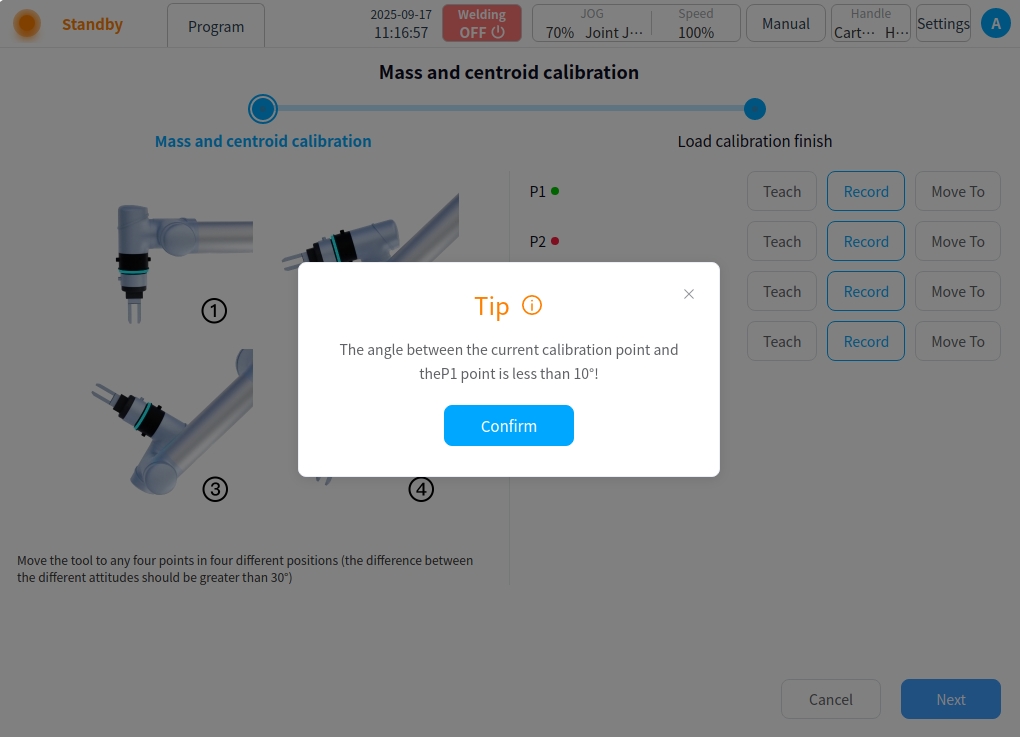
After the JOG robot reaches the target point, click “Record Current Point”, the interface will jump back to the TCP calibration process interface, and after teaching a calibration point, the red dot after the corresponding calibration point will turn green. You can also use the physical buttons of the tutor to direct the JOG robot to the target point, and then click “Record Current Point” on the calibration page directly. In the process of teaching, if the current teaching point does not meet the limitations, a pop-up box will be prompted as shown below.

After teaching all the points of P1-P4 in turn, click the “Next” button at the bottom right corner of the calibration process page to enter the TCP attitude calibration stage.There are two forms of TCP attitude calibration: customized and two-point setup, the default is customized as shown in the figure below. The default is customized, as shown in the figure below.
After setting the axial deflection angle of the flange coordinate system corresponding to the tool, click the “Next” button to complete the calibration stage as shown in the figure below, which will display the calibration results and error information. Users can judge the quality of the calibration by the error information, so as to decide whether to load this coordinate system. If you need to load this coordinate system, click “Confirm” button. The information about the calibrated tool coordinate system will be displayed on the TCP calibration page, and the calibrated TCP result will be added to the tool coordinate system list and set as the default and current tool coordinate system; Otherwise, click the “Cancel” button, or click “Previous” to return to reteach the point.

Caution
The error value of the calibration result, the real meaning is the standard deviation of the distance between the calculated TCP position and the 4 calibration points. This data can be used as a reference for the calibration result, but cannot be used as an absolute basis for the calibration accuracy, the actual accuracy is subject to the application effect.
The calibration results of TCP are usually based on an average error of less than 2mm.
When “Two Points Setting” is selected in the TCP Attitude Calibration stage, as shown in the figure below, the available options for point P5 are O-P5 for X+direction/Y+direction/Z+direction of the tool coordinate system. The corresponding options for point P6 are O-P5-P6 for tool coordinate system XOY plane/XOZ plane, O-P5-P6 for tool coordinate system XOY plane/YOZ plane, and O-P5-P6 for tool coordinate system XOZ plane/YOZ plane. Take the order of O-X-Y-Z axis to determine the attitude of the tool coordinate system as an example: point O is the current location of the tool position, first of all, along the expected tool coordinate system X + direction of the tool position to move to the point P5, then along the expected tool coordinate system Y + direction of the tool position to move to the point P5. Then move the tool position along the desired tool coordinate system Y+ direction to point P6.

After setting up P5 and P6, click the “Next” button to enter the calibration stage, which will display the calibration result and error information. The user can judge the quality of the calibration by the error information, and decide whether to load this coordinate system or not. Similarly, if you want to load this coordinate system, click “Confirm” button, otherwise click “Cancel” button. Otherwise, click the Cancel button, or click Previous to go back and retest the points.
Click the “Confirm” button to return to the Add Tool page, and the coordinate system information displays the calibrated coordinates as shown in the figure below.
Load information Load information allows you to set the mass and coordinates of the load item, which can be obtained by manual input or load recognition. For manual input, enter the coordinates directly into the input box. If you need to recognize the load, click Load Recognition on the right side to enter the Load Recognition page. Record according to the posture shown in the figure, and refer to the above TCP calibration process, as shown in the figure below:
After the points are recorded, click Next to view the identification results and click OK when the results are correct.
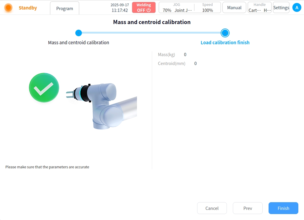
If the attitude of each point is recorded incorrectly, an error will be indicated and you will be asked to repeat the recording;
After the tool name, coordinate system information, and load information are set, click the Finish button to return to the Tool TCP list, where you can view the added tool TCP information.
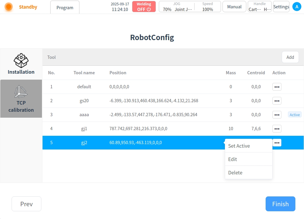
Click ‘…’ after the tool TCP list. Operation button, you can set as current, edit and delete operations.
Set to current: Set this tool TCP to the current system’s tool TCP.
Edit: Edit tool TCP information.
Delete: Delete tool TCP information.