process library#
The Process Library page is used to manage all process files within the currently active project. The left side displays the list of processes and the right side displays the contents of the currently selected process.
In the advanced mode, click on the user’s avatar, select “Process Library” to enter the process library page, if there is no process, it will be blank, you need to click on the lower left corner of the new or import to add process.
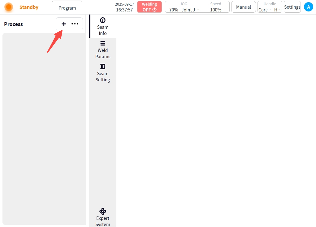
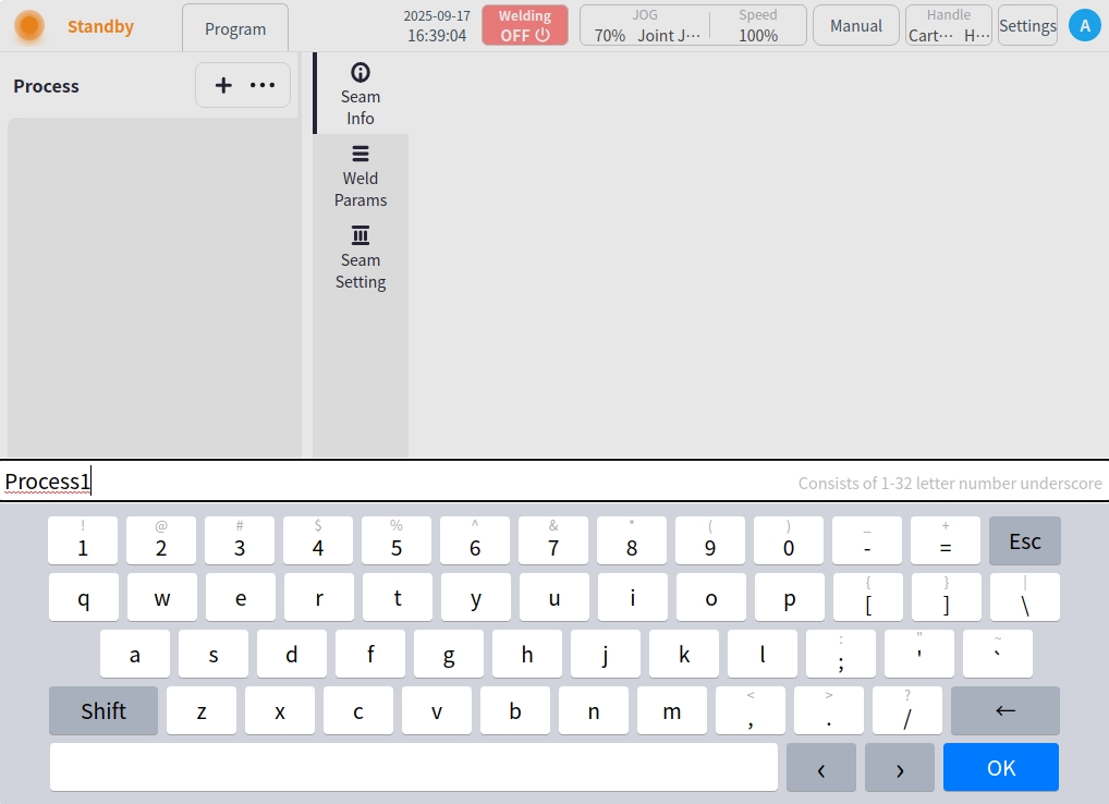
New: Clicking New will automatically generate the process name, which can also be modified as appropriate. Click the ‘OK’ button to complete the process addition.
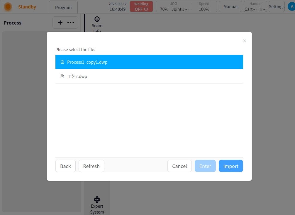
Import: Click ‘…’ Select Import, a USB flash drive file selection box will pop up, select the corresponding process file and click ‘Import’ button to complete the process import.
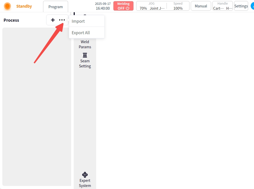
Export All: Click the Export All button to export the current list of craft files to a USB flash drive.
Process List#
The list of crafts can be displayed on the left side of the page after successful addition;
The process items in the list provide part of the process information display and operation as follows:

Shown above from left to right are: serial number, process type, process name, lock icon, and operation icon;
Serial Number: Displays the serial number of the craft in the list;
Process Type: When the icon displays  , the process is a single-pass process; when the icon displays
  , the process is a multi-pass process;
Process name: Display process name;
Lock icon: When the icon displays  , the process is locked; when the icon displays
  , the process is not locked;
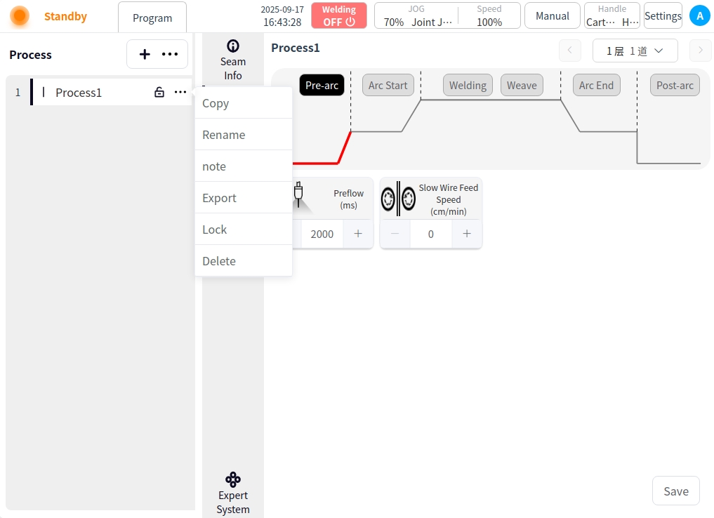
Operation Icons: Click on the icons to enter the craft for copy, rename, note, export, lock/open, and delete operations;
Copy: Click “Copy” to bring up the keyboard, the process name to be copied will be suffixed with “_copyxx” by default, users can also modify and rename it according to the naming rules of the process file; click ‘OK’ to save. Click ‘OK’ to save.
Rename: Click “Rename” to pop up the keyboard, input the new process name, OK to modify;
Remarks: Click “Remarks” to bring up the keyboard, enter the new process remarks;
Export: Click “Export” to export the process file to USB flash disk;
Lock/open: you can lock or open the process file. Lock/open: you can lock or open the process file. You cannot delete or rename the current process after locking;
Delete: click “Delete”, a confirmation dialog box will pop up, and the process file can be deleted after confirmation;
Process content#
Select any data in the process list on the left to view and set the content of the process. The content area is divided into: Weld Information, Welding Parameters, Weld Path Configuration, and Expert System;
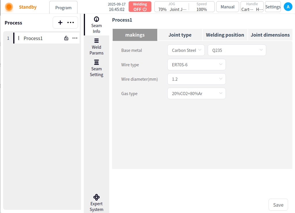
Weld Information#
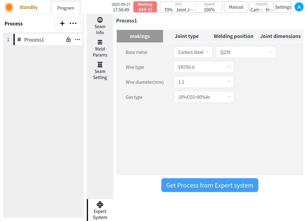
Click on Weld Information. You can set the material, joint type, welding position, and joint size of the workpiece to be welded by the current process. Click Save when the settings are complete;
Material: Welding base material, wire type, wire diameter, and shielding gas type can be set;
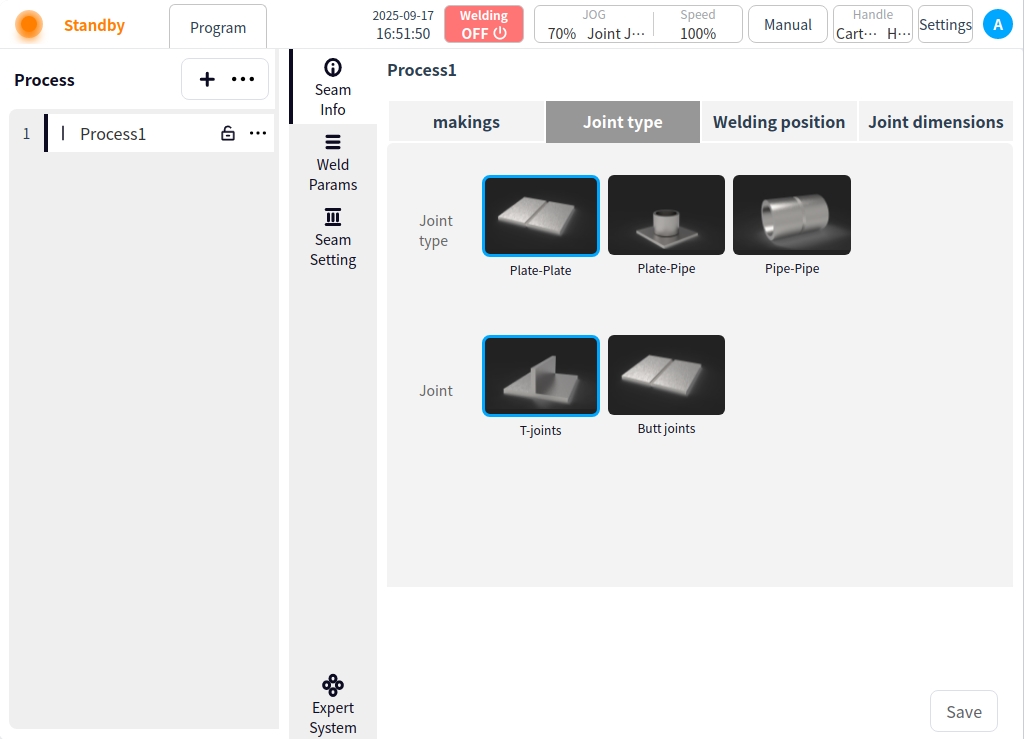
Connector type: Connector type and connector form can be set;
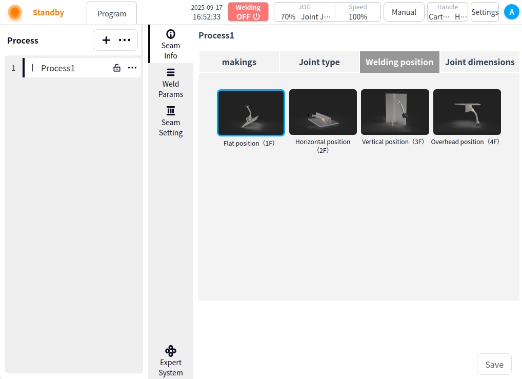
Welding position: Flat, horizontal, vertical and backward welding can be selected;
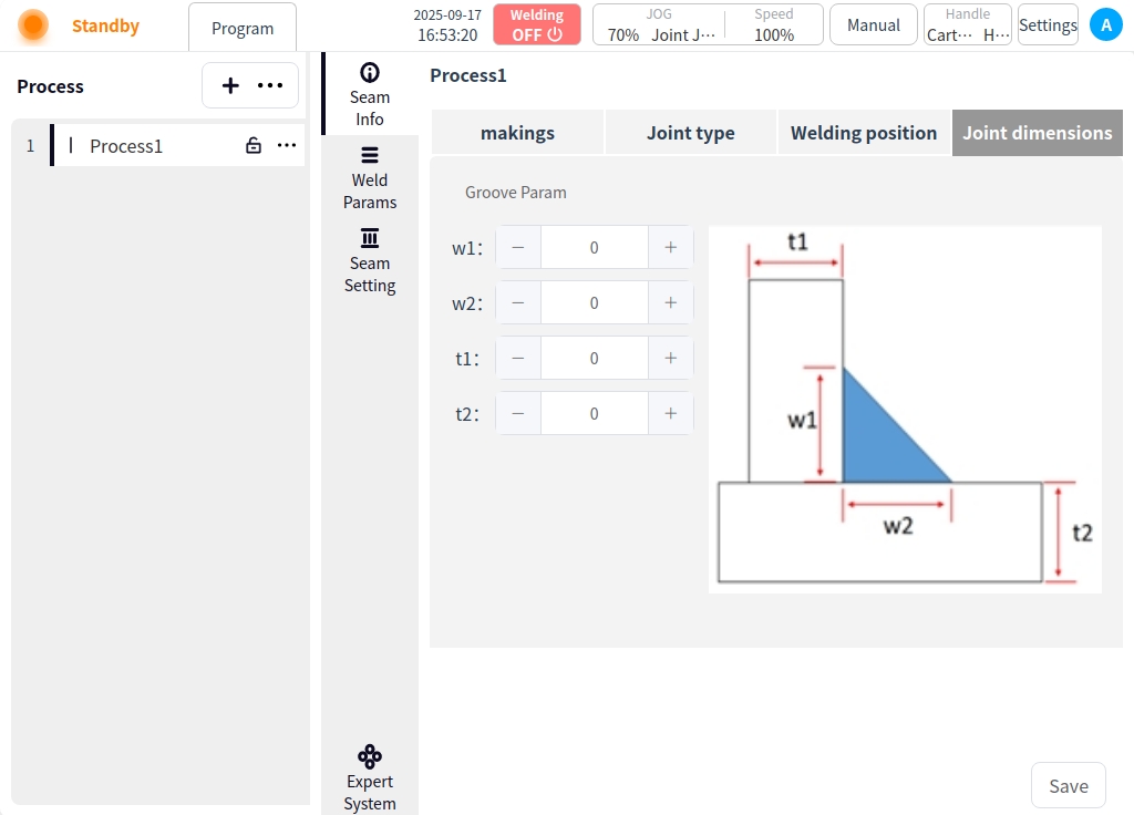
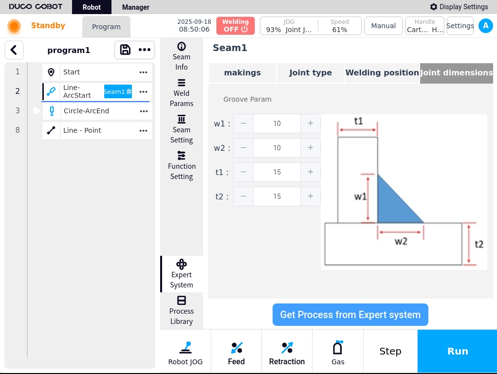
Joint size: w1, w2, t1, t2 settings are available;
Weld Path Setting#
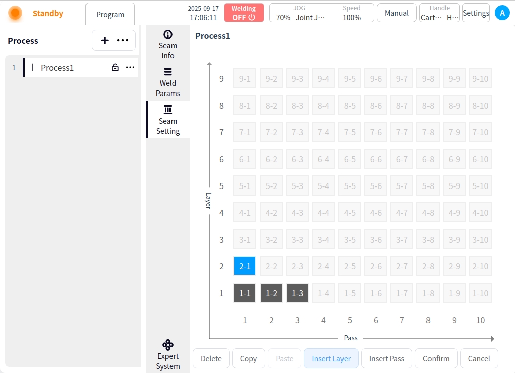
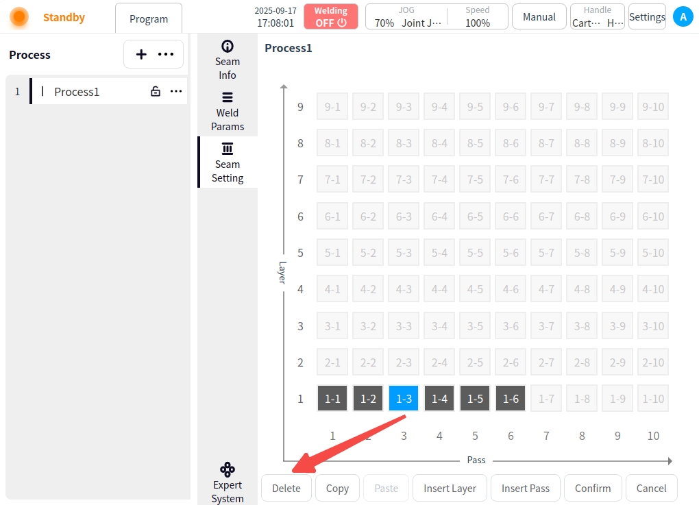
Click Weld Path Setting. In the Weld Path Setting page, you can create, copy, paste, insert layers, insert paths, delete, etc. for the current process weld, as follows:
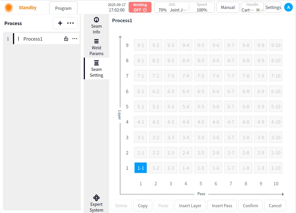
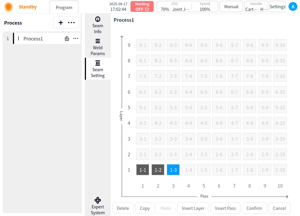
New Weld Path: Click on an uncreated cell in the grid to add a new weld path.
If there is a weld channel in the current layer, additional channels are added backward according to the clicked grid; for example, if 1-1 already exists, and 1-5 is clicked at this time, the grids between 1-1 and 1-5 are created; and
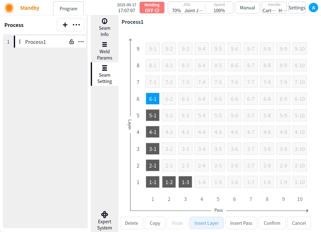
If there is no weld channel in the current layer, the first grid will be created in turn; for example, 1-1 already exists, click 4-1 at this time, then 1-1, 2-1, 3-1, 4-1 will be created;
Combining the above two cases, clicking on any grid, the channel of the layer where it is located, the layer below the layer where it is located is created; for example, 1-1 already exists, at this time, clicking on 4-3, then 2-1, 3-1, 4-1, 4-2, 4-3 are created;
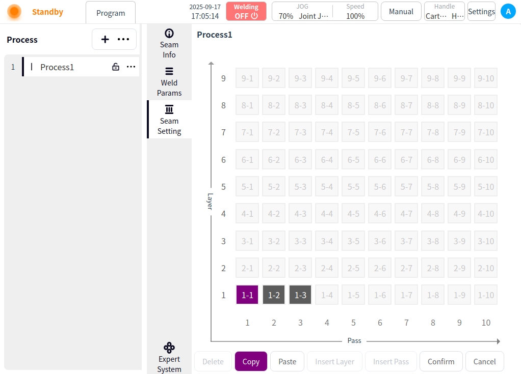
Copy: Click the Copy button for copy target selection;
Click on the Copy button → for copy target selection; (the selected weld channel is marked in dark purple);
Once the copy mode is turned on, clicking on the weld channel is the selection of the copy target;
Click on the Copy button again to exit the copy target selection;
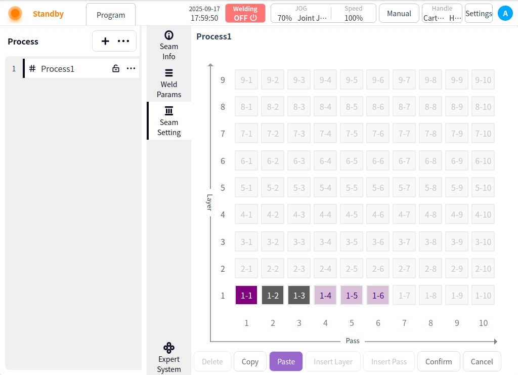
Paste: After selecting the copy target, click the Paste button to exit the copy target selection and enter the paste mode;
Select the target for copying → click the Paste button to enter the paste mode;
After entering the paste mode, click on any weld channel to paste it (the weld channel after pasting is marked in light purple color);
Click the Paste button again → exit Paste mode;
In the paste mode, if you want to switch the copy target, click the copy button again to select the copy target;
Insertion level:
Insert a new layer (layer-1) above the selected layer;
Pan the subsequent weld paths and renumber them;
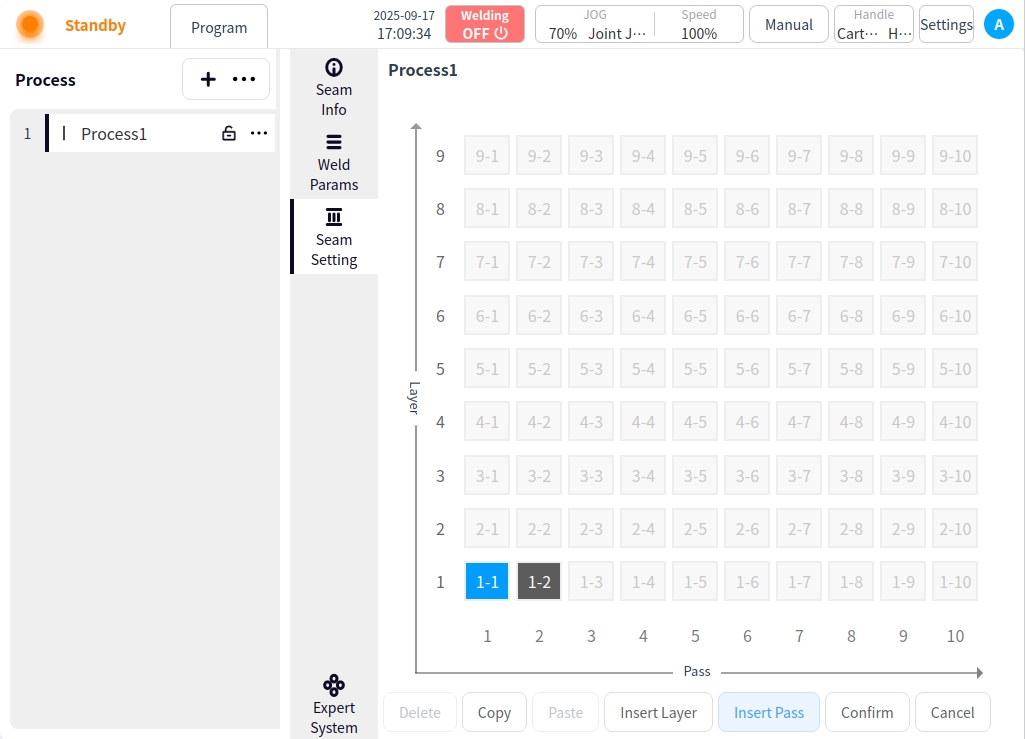
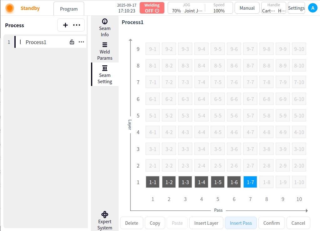
Insert channel:
Insert a new weld channel to the right of the selected weld channel;
Move subsequent weld passes to the right and renumber them;
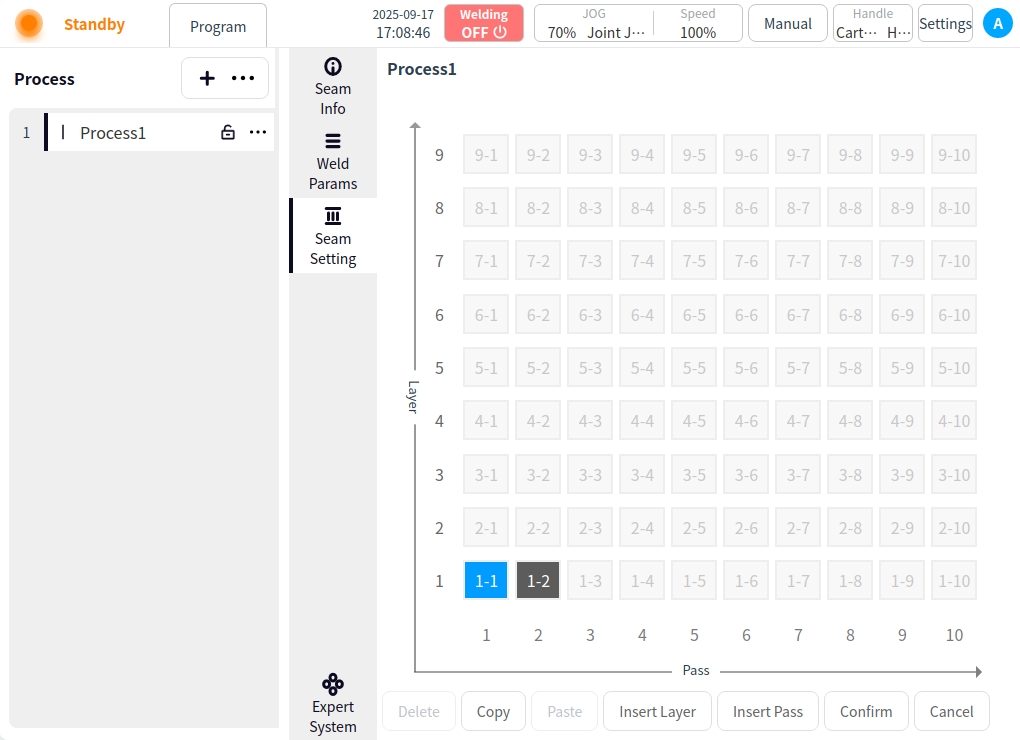
Delete: Delete weld channel;
Select the created weld channel and click Delete;
If the deletion is of the first weld line in the layer, the entire layer is deleted; subsequent layers are panned uniformly;
If the deletion is of a weld line in the middle of a layer, the weld line and subsequent weld lines are deleted;
OK: Click OK to save;
Welding parameters (gas welding)#
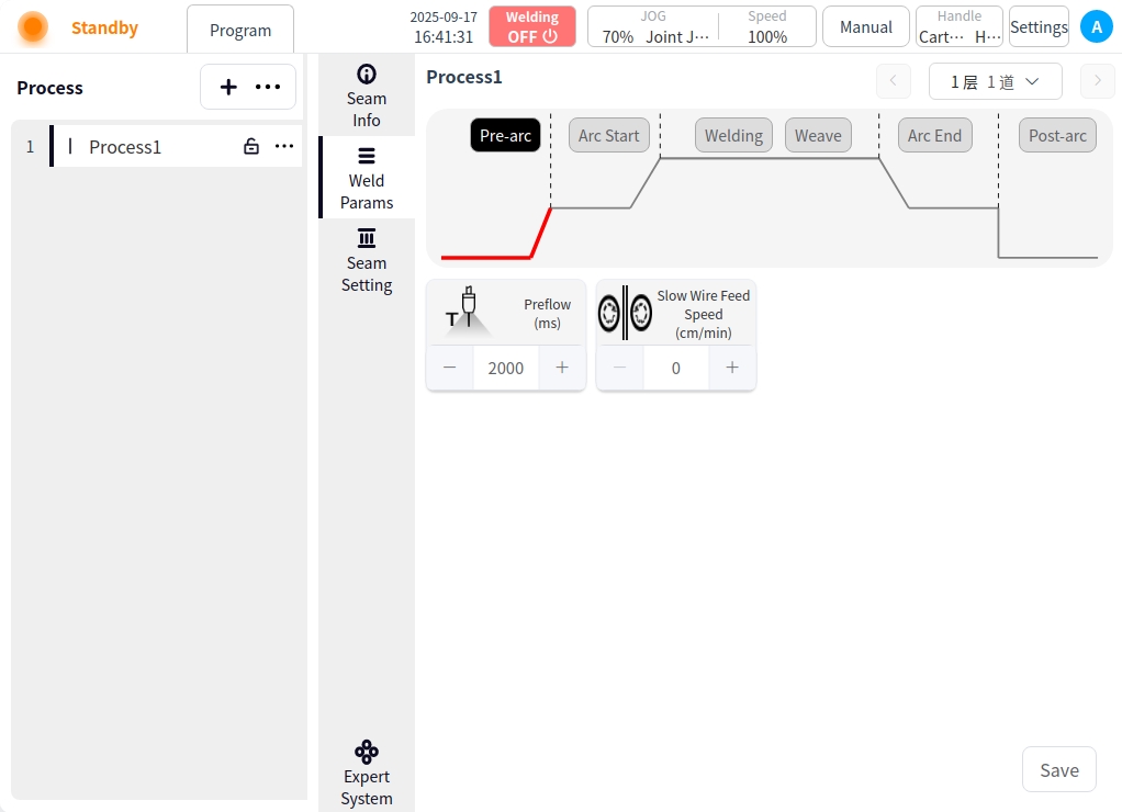
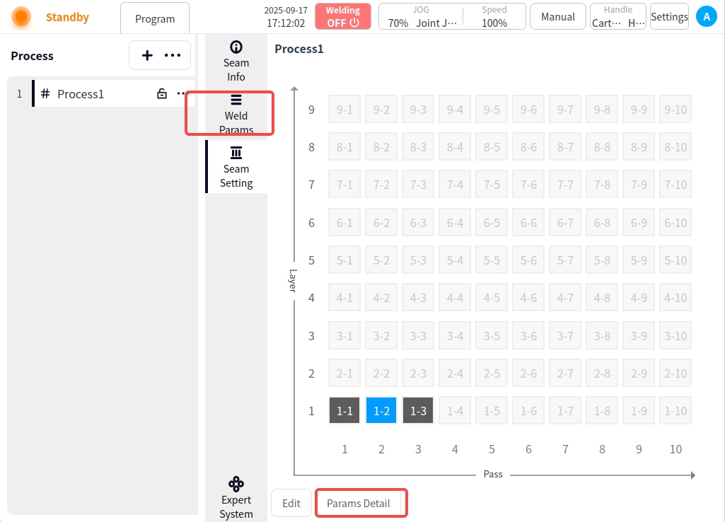
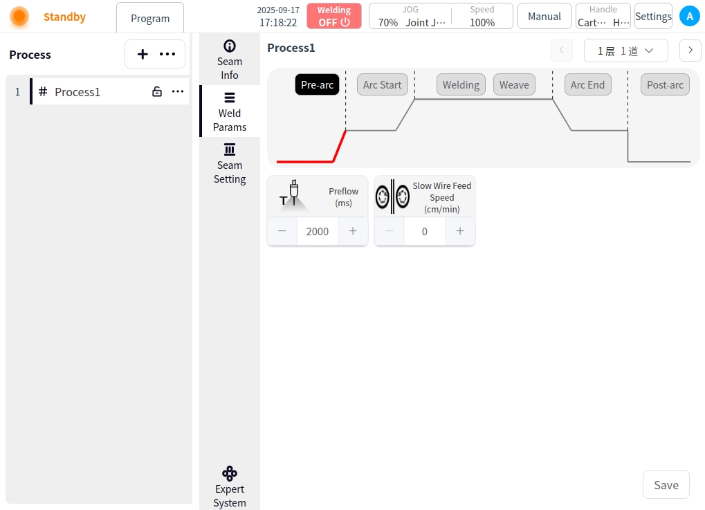
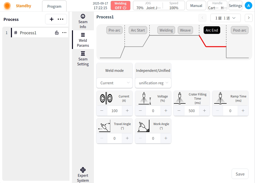
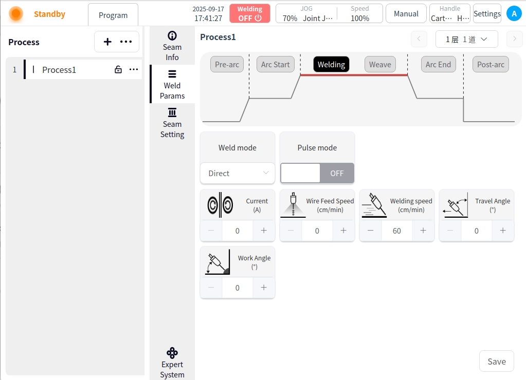
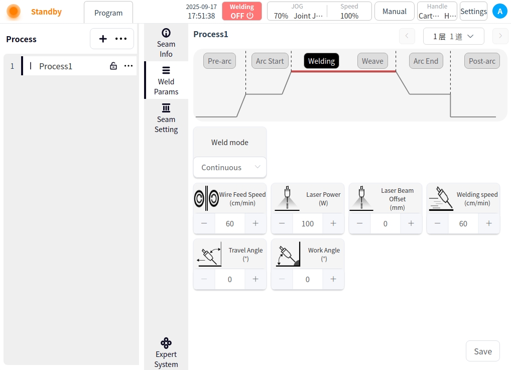
Click the Weld Parameters button to enter the Weld Parameters page. Or click the parameter details in the weld channel setting page to enter the welding parameter page of the selected weld channel. In the welding parameter page, you can configure the parameters of each stage of the process, such as before arc starting, arc starting, welding, swing welding, arc closing, and after arc closing, and click the corresponding buttons in the picture to switch the parameters of each stage. In the Welding Parameters page, you can click the button at the upper right corner to switch the welding channel, or click the drop-down selection box to switch the welding channel selection.
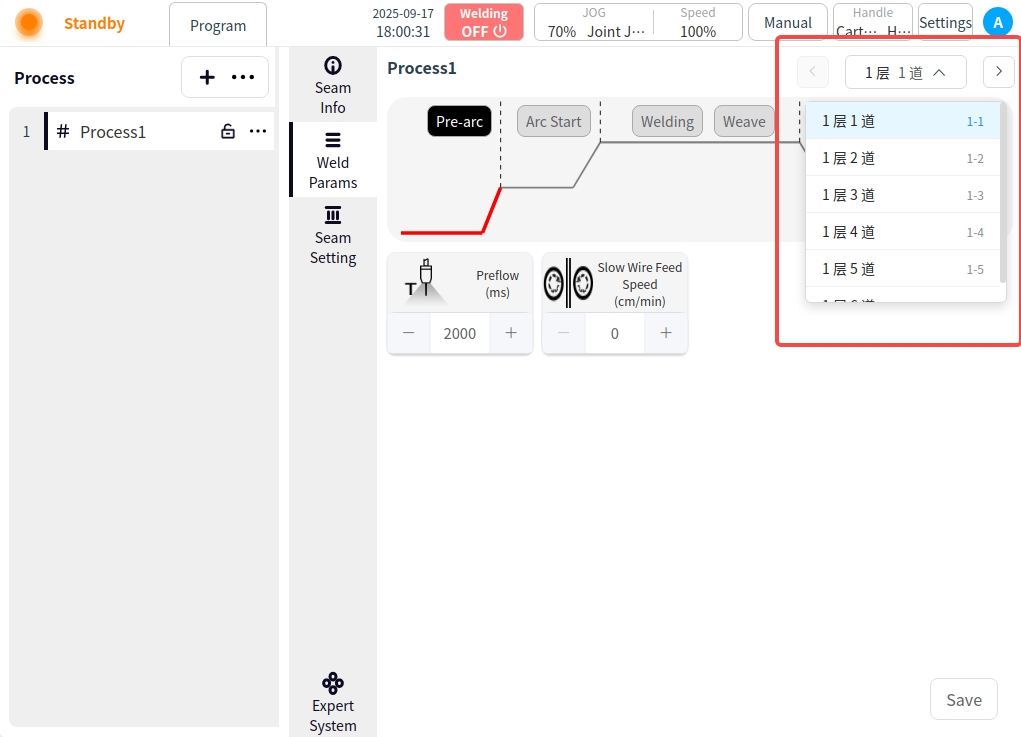
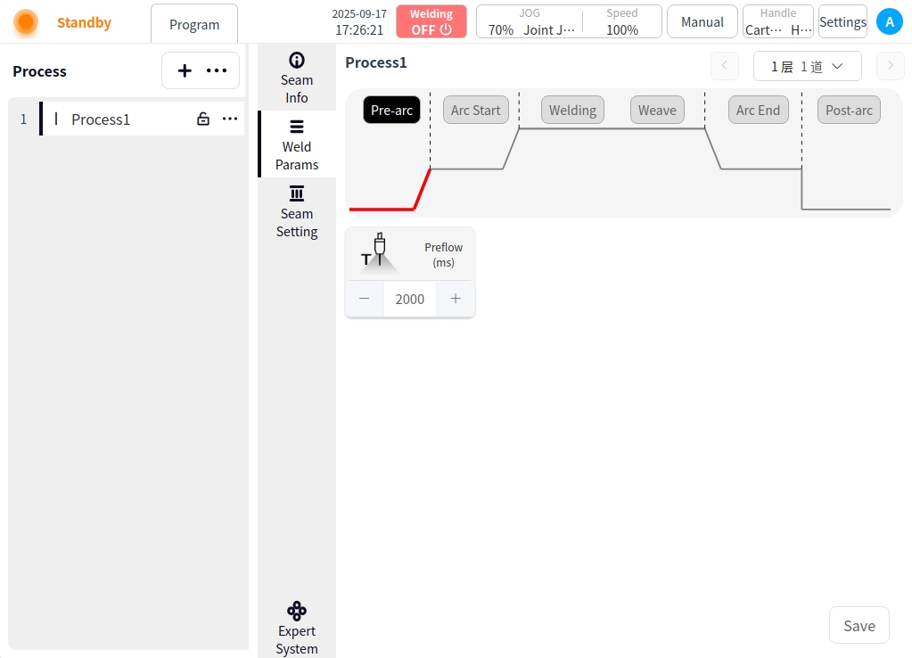
Pre-Arc: Click on the Pre-Arc button to configure the Pre-Arc parameters;
Pre-feeding time: the time to start sending shielding gas before starting the arc, in ms.
Slow wire feeding speed: refers to the instant before the arc is formally ignited, the welder controls the wire feeding mechanism to send out the wire at a lower speed than normal welding, unit cm/min.
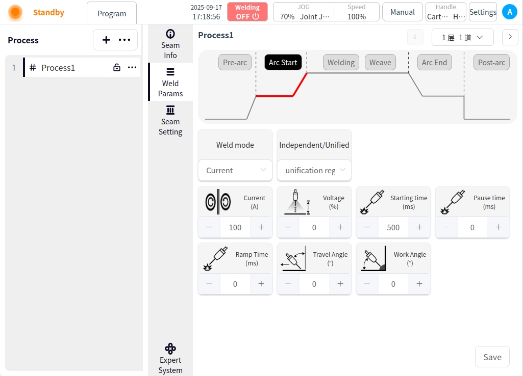
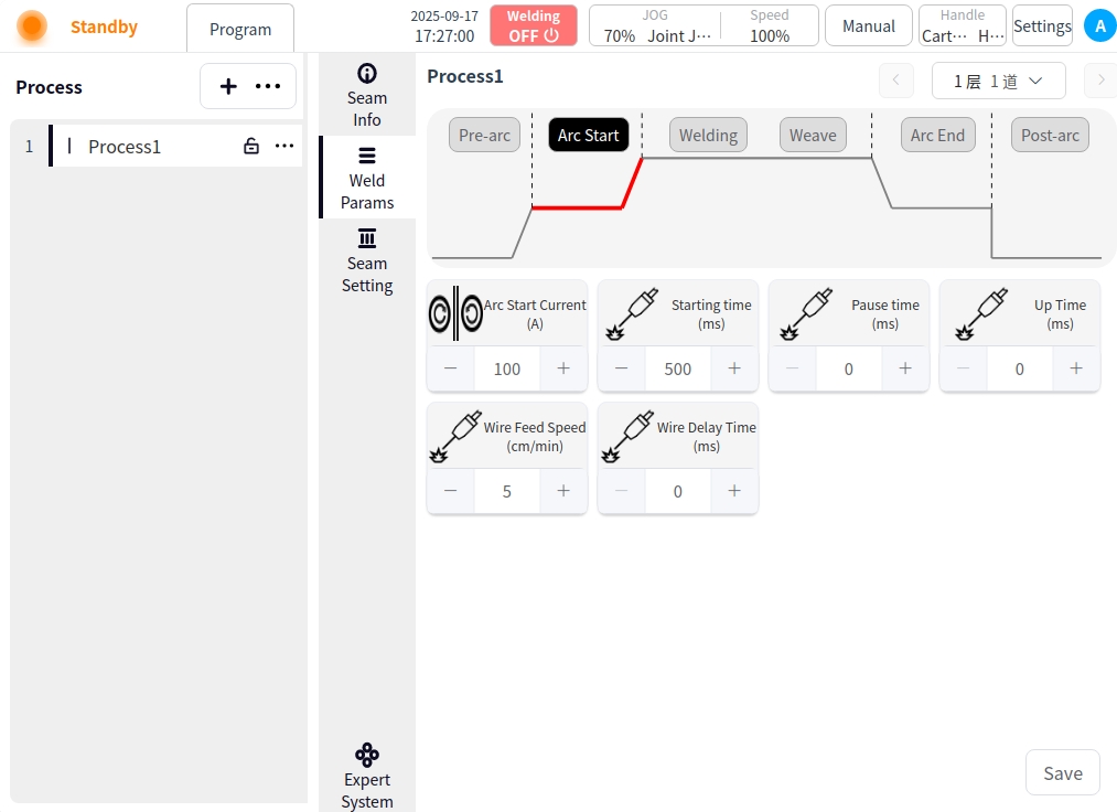
Arc Start: Click the Arc Start button to configure the parameters for arc start;
Welding mode: Used to set the working mode of the arc starting stage of the welding torch, including: standard, JOB mode;
Independent / one-dimensional mode: independent mode is the welding current and voltage are given separately; one-dimensional mode is the welding voltage is automatically matched by the welder according to the current, you can specify the size of the voltage adjustment;
Arc current: the value of welding current in the arc starting stage, unit is A;
Arc voltage: the value of welding voltage at the arc starting stage, unit is V;
Arc start time: the time for welding with the arc start parameter after successful arc start;
Arc pause time: the time that the robot stays in place at the arc starting point after successful arc starting;
Gradient time: the time required for the welding parameters to smoothly transition from the initial value to the set value during the arc start phase;
Forward angle: the angle in the plane parallel to the welding direction in which the torch is tilted in the direction (pushed or pulled);
Working angle: perpendicular to the plane of the welding direction, the angle between the torch and the plane of the workpiece;
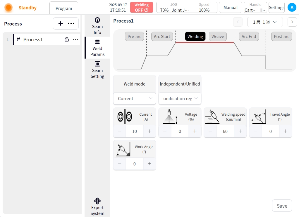
Welding: Click the Weld button to configure the parameters for welding;
Welding Mode: Used to set the working mode of the welding stage of the torch, including: standard, JOB mode;
Independent/monotonic mode: independent mode is that the welding current and voltage are given separately; monotonic mode is that the welding voltage is automatically matched by the welder according to the current, and the adjustment size of the voltage can be specified;
Welding current: welding current value, unit A;
Welding voltage: welding voltage value in V;
Welding speed: the running speed of the welding torch during the welding process;
Forward angle: parallel to the plane of the welding direction, the angle of the welding torch tilt direction (push or pull);
Working angle: perpendicular to the plane of the welding direction, the angle between the welding torch and the plane of the workpiece;
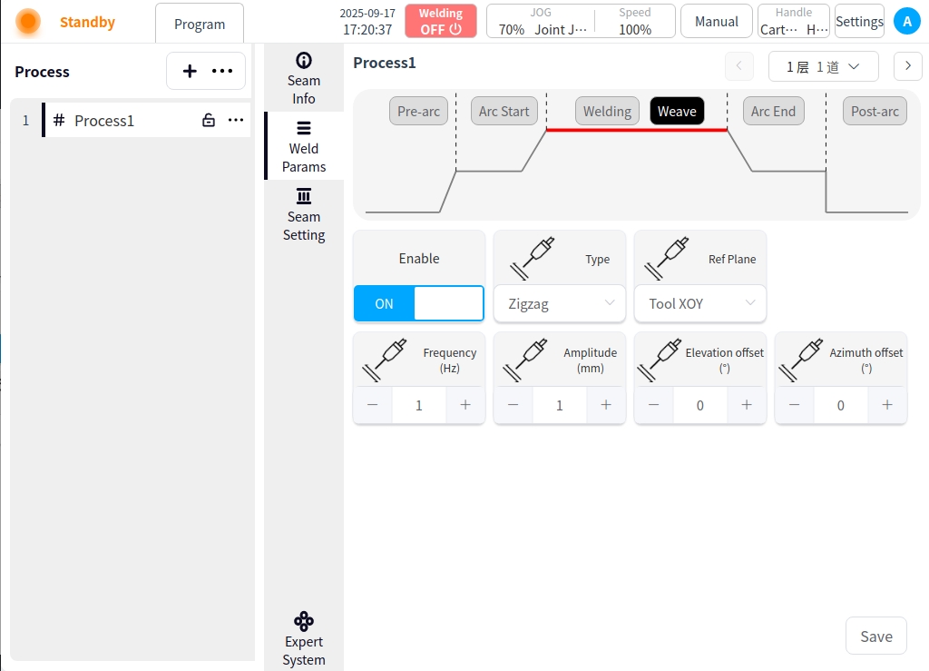
Pendulum Welding: Click the Pendulum Welding button and turn on Pendulum Welding to configure the parameters for pendulum welding;
Pendulum Welding Setting Enable Button: Used to enable or disable pendulum welding;
Pendulum Welding Type: There are 7 types of pendulum welding: Sawtooth, Triangle, Sine, Arc, Trapezoid, ‘8’ and Reciprocating;
Reference Plane: the plane of reference for the pendulum welding process can be selected as: Tool XOY, Tool XOZ, Tool YOZ, Workpiece XOY, Workpiece XOZ, Workpiece YOZ;
Oscillation frequency: set the frequency of the oscillation welding process, unit HZ;
Oscillation amplitude: set the amplitude in the process of pendulum welding, unit m;
Left dwell time: only when the pendulum welding mode is selected as sinusoidal or trapezoidal, the parameter needs to be configured, the unit is ms;
Right dwell time: a parameter to be configured only when the pendulum welding mode is selected as sinusoidal or trapezoidal, the unit is ms;
Main path synchronized stay: only when the welding mode is sinusoidal or trapezoidal, the parameter needs to be configured, the default is unchecked; when the parameter is checked, the main path of the robot movement can be stopped at the same time during the left and right stay;
Elevation angle offset: refers to the tilt angle of the torch’s axis relative to the standard working angle (usually 90° perpendicular to the surface of the workpiece) in the plane perpendicular to the welding direction;
Directional angle offset: the angle of deflection of the torch’s axis relative to the weld centerline in a plane parallel to the welding direction;
Forward distance: means the distance moved along the main direction of welding when the welding torch swings from the center line to the farthest point reached from one side. Backward distance: means the distance moved along the main direction of welding when the welding torch swings from the center line to one side;
Backward distance: refers to the welding torch from one side of the farthest point swung back to the center line (or the other side), along the main direction of welding distance;
Arc closing: Click the Arc Closing button to configure the parameters for arc closing;
Welding mode: Used to set the working mode of the arc closing stage of the welding torch, including: standard, JOB mode;
Independent / one-dimensional mode: independent mode is the welding current and voltage are given separately; one-dimensional mode is the welding voltage is automatically matched by the welder according to the current, you can specify the size of the voltage adjustment;
Arc closing current: the value of welding current at arc closing stage, unit is A;
Arc closing voltage: the value of welding voltage at arc closing stage, unit is V;
Arc closing time: the time to weld with arc closing parameters after starting arc closing;
Gradient time: the time required for the welding parameters to smoothly transition from the initial value to the set value during the arc starting stage;
Forward angle: parallel to the plane of the welding direction, the angle of the torch tilt direction (push or pull);
Working angle: perpendicular to the plane of the welding direction, the angle between the torch and the plane of the workpiece;
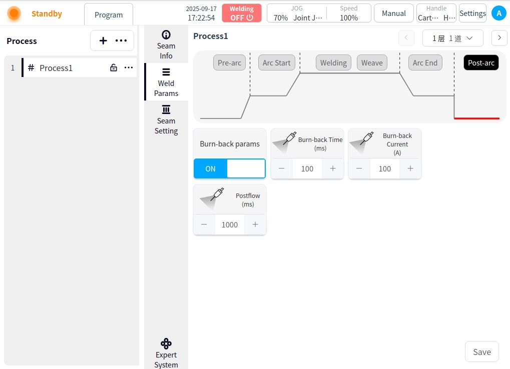
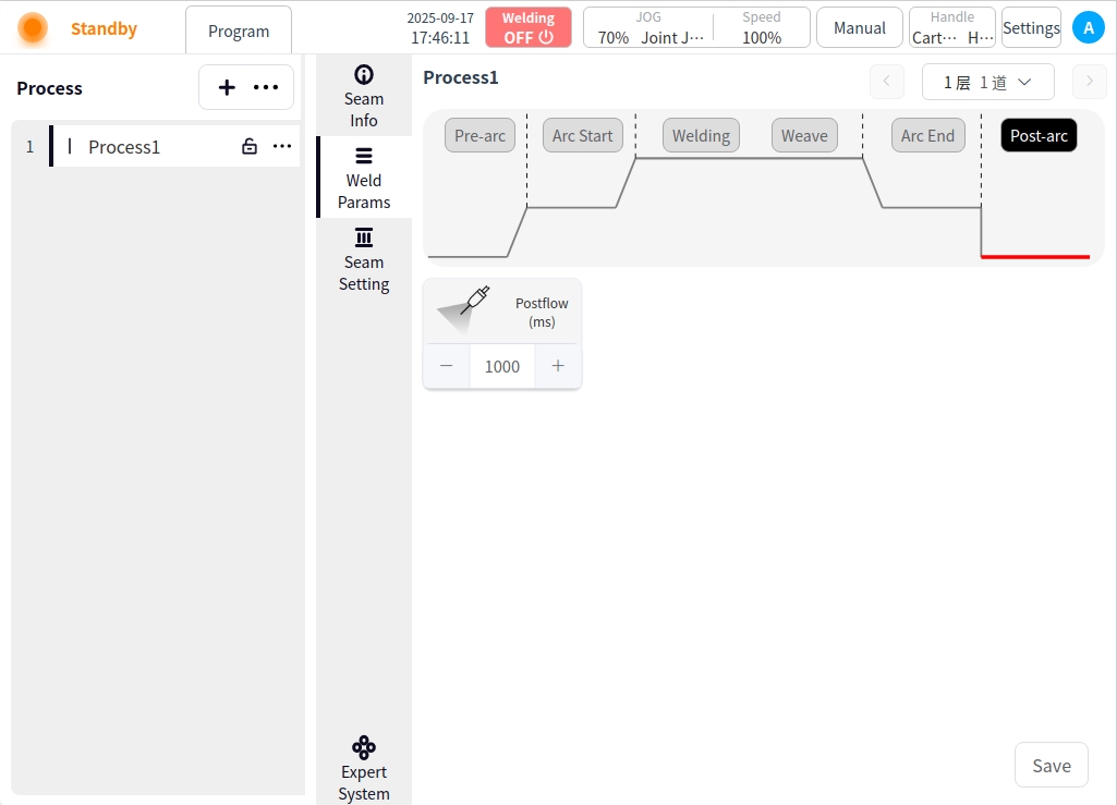
After Arc Close: Click the After Arc Close button to configure the parameters of the after arc close;
Burnback Parameter Enable Button: used to enable or disable burnback;
Burnback time: burnback time of the burnback parameter;
Burnback current: burnback current of burnback parameter;
Delayed Gas Delivery Time: the time to delay stopping and delivering gas after all welding work is completed;
Process Editor (TIG welding)#
Pre-Arc: Click on the Pre-Arc button to configure the Pre-Arc parameters;
Pre-feeding time: the time to start feeding the protective gas before starting the arc, in ms.
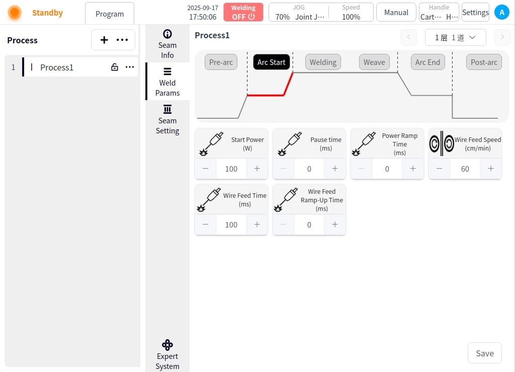
Arc Start: Click the Arc Start button to configure the parameters for arc start;
Arc current: the value of welding current in the arc starting stage, in A;
Arc start time: the time to use the arc start parameter to weld after successful arc start;
Arc pause time: the time the robot stays in place at the arc starting point after successful arc starting;
Slow rise time: the time required for the initial current/voltage of arc ignition to rise smoothly to normal welding parameters;
Wire feed speed: the wire feed speed at the start of the arc, the unit is cm/min;
Wire feed delay time: the time to delay the wire feed speed when starting the arc;
Welding: Click the Weld button to configure the parameters for welding;
Welding Mode: Used to set the working mode of the welding stage of the torch, including: Standard, JOB mode;
Pulse mode: switching pulse mode;
Welding current: the value of welding current, unit is A;
Wire feeding speed: the wire feeding speed when starting arc, unit is cm/min;
Welding speed: the running speed of the welding torch during the welding process;
Forward angle: parallel to the plane of the welding direction, the angle of the tilting direction of the welding torch (push or pull);
Working angle: perpendicular to the plane of the welding direction, the angle between the torch and the plane of the workpiece;
Peak current: the highest current value in the pulse cycle, producing a high intensity arc;
Base Current: the lowest maintenance current in the pulse cycle, lower than the normal welding current;
Frequency: number of pulse cycles completed per second (in Hz);
Duty Cycle: peak current duration as a percentage of a pulse cycle;
Peak Wire Delivery Speed: the wire delivery speed during the peak current phase;
Base wire speed: the wire delivery speed during the base current phase;
Pendulum Welding: Click the Pendulum Welding button and turn on Pendulum Welding to configure the parameters for pendulum welding;
Pendulum Welding Setting Enable Button: Used to enable or disable pendulum welding;
Pendulum Welding Type: There are 7 types of pendulum welding: Sawtooth, Triangle, Sine, Arc, Trapezoid, ‘8’ and Reciprocating;
Reference Plane: the plane of reference for the pendulum welding process can be selected as: Tool XOY, Tool XOZ, Tool YOZ, Workpiece XOY, Workpiece XOZ, Workpiece YOZ;
Oscillation frequency: set the frequency of the oscillation welding process, unit HZ;
Oscillation amplitude: set the amplitude in the process of pendulum welding, unit m;
Elevation angle offset: refers to the tilt angle of the welding torch’s axis in the plane perpendicular to the welding direction relative to the standard working angle (usually 90° perpendicular to the surface of the workpiece);
Direction angle offset: refers to the welding torch in the plane parallel to the welding direction, its axis relative to the weld centerline deflection angle;

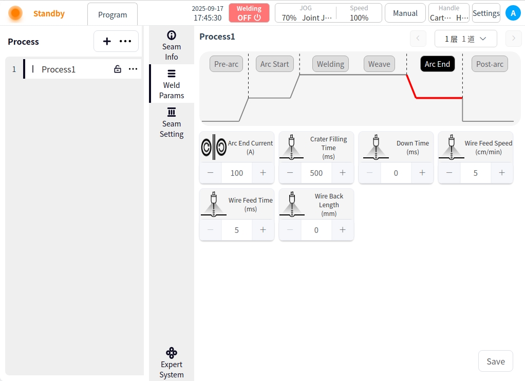
Arc closing: Click the Arc Closing button to configure the parameters for arc closing;
Arc closing current: the value of welding current in the arc closing stage, in A;
Arc closing time: the time of welding with arc closing parameters after starting arc closing;
Wire feed speed: the wire feed speed at the start of the arc, in cm/min;
Wire feed time: the wire feed time at the start of the arc;
Trailing time: the period of time elapsed during which the welding current is gradually (linearly or non-linearly) reduced from the normal welding current to a lower current (usually the arc closing current or zero);
Forward Angle: the angle in the plane parallel to the welding direction in which the torch is tilted (pushed or pulled);
Working angle: the angle between the torch and the plane of the workpiece in the plane perpendicular to the welding direction;
Welding wire recovery length: after closing the arc, the displacement length of the welding wire recovery to the welding torch;
After Arc Close: Click the After Arc Close button to configure the parameters of the after arc close;
Delayed Gas Feed Time: The time for delayed shutdown and gas feed after all welding work is completed;
Process Editor (Laser Welding)#
Pre-Arc: Click on the Pre-Arc button to configure the Pre-Arc parameters;
Pre-feeding time: the time to start feeding the protective gas before starting the arc, in ms.
Arc Start: Click the Arc Start button to configure the parameters for arc start;
Open power: the initial power of the laser output in the arc starting stage, usually lower than the normal welding power;
Arc start pause time: the robot after the successful start of the arc in place at the starting point of the time;
Slow rise time: the laser power from the initial value of the arc rise to the normal welding power time required;
Wire feed speed: the wire feed speed at the start of the arc, the unit is cm/min;
Wire feeding time: the wire feeding time at the start of the arc;
Wire feed slow rise time: in the arc stage, the wire feed speed from zero gradually increased to the set value of time;
Welding: Click the Weld button to configure the parameters for welding;
Welding Mode: Used to set the working mode of the welding stage of the torch, including: continuous, modulation mode;
Laser power: laser power is the energy output from the laser;
Laser center offset: the laser beam focus relative to the center of the weld offset distance;
Wire feed speed: the wire feed speed at the start of the arc, in cm/min;
Welding speed: the running speed of the welding torch during the welding process;
Forward angle: parallel to the plane of the welding direction, the angle of the welding torch tilt direction (push or pull);
Working angle: the angle between the torch and the workpiece plane in the plane perpendicular to the welding direction;
Frequency: number of pulse cycles completed per second (in Hz);
Duty Cycle: the duration of peak current as a percentage of a pulse cycle;
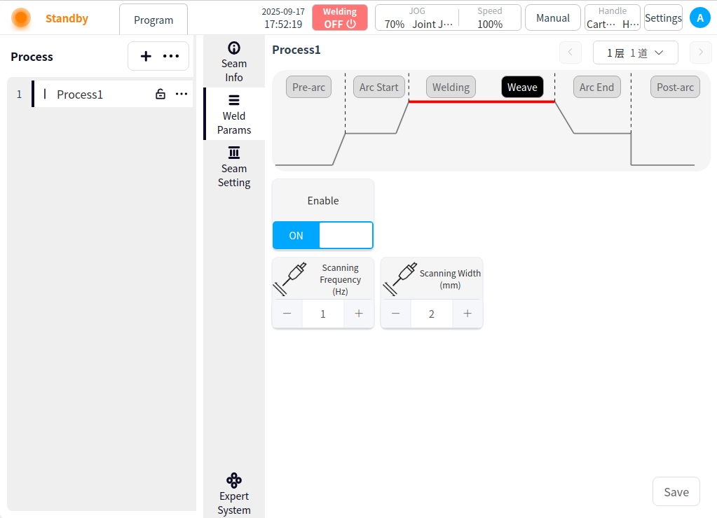
Pendulum Welding: Click the Pendulum Welding button and turn on Pendulum Welding to configure the parameters for pendulum welding;
Pendulum Welding Setting Enable Button: for whether to enable pendulum welding;
Scanning Frequency: Scanning Frequency is the number of times the laser beam completes the swing in the swing track per unit time;
Scanning Width: Scanning width is the maximum lateral deviation distance of the swing track of the laser beam;
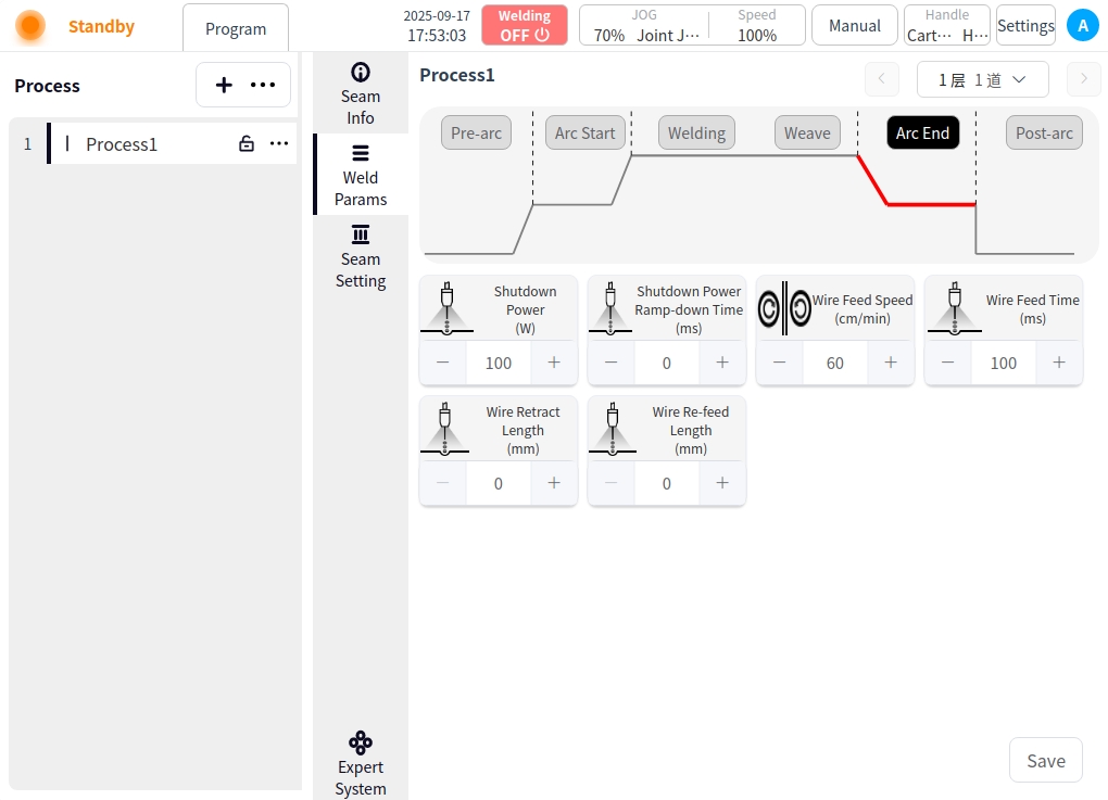
Arc closing: Click the Arc Closing button to configure the parameters for arc closing;
Off-light power: the final power value when the laser power is gradually reduced to zero during the arc closing stage;
Off light power slow down time: laser power from the normal welding power down to off light power time required;
Wire feeding speed: the closing arc wire feeding speed, unit is cm/min;
Wire feeding time: the wire feeding time when closing the arc;
Welding wire recovery length: after closing the arc, wire recovery to the displacement length of the torch;
Repeat wire feeding length: the arc closing stage of the wire continues to feed the length of the molten pool (from the beginning of the slow decline in laser power to the complete shutdown period);
After Arc Close: Click the After Arc Close button to configure the parameters of the after arc close;
Delayed Gas Feed Time: The time for delayed shutdown and gas feed after all welding work is completed;
Multi-layer and multi-channel process editing#
Multi-layer channel process editing adds an interlayer message to all channels except the first;
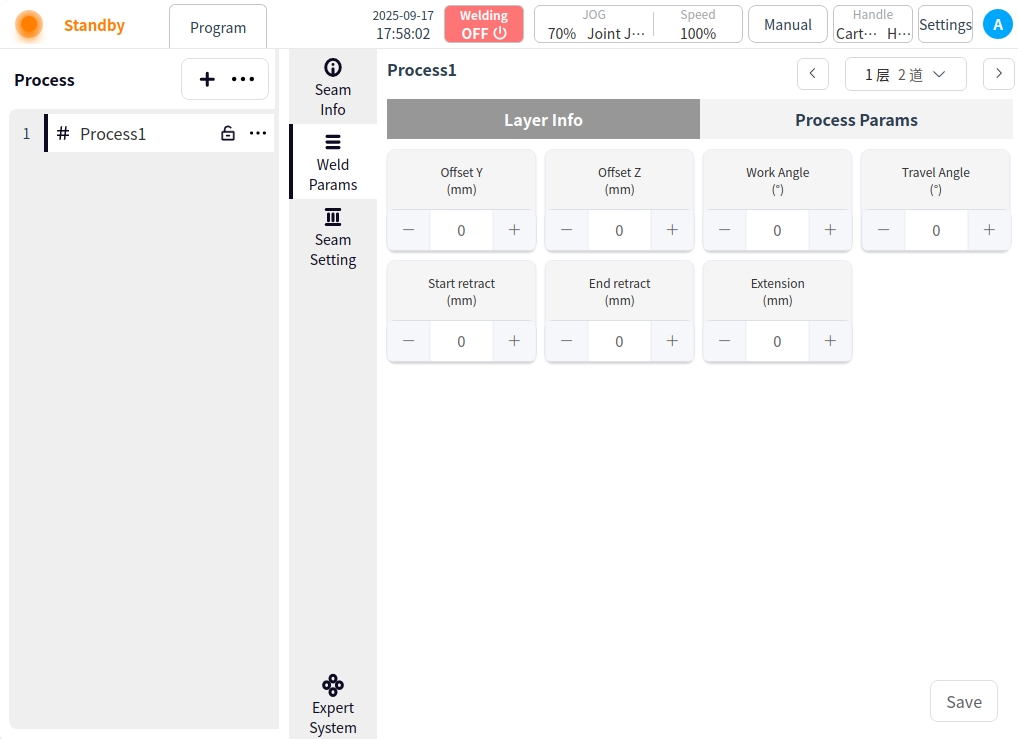
Interstorey information:
Y offset: the offset of the welding torch in the horizontal direction (Y axis) with respect to the center of the first weld;
Z offset: the offset of the welding torch in the vertical direction (Z axis) with respect to the surface of the first weld;
Tilt angle: the angle between the welding torch and the surface of the workpiece;
Push-pull angle: the angle between the direction of movement of the torch and the direction of the weld;
Start indentation: the distance the torch retracts when starting the arc;
End point indentation: the distance back when the torch closes the arc;
Dry elongation: the distance from the end of the wire to the surface of the workpiece;
Click on the Save button in the lower right corner after editing the current weld procedure to save it;
expert system#
Click on Expert Systems. Go to the Expert System page; Before using the Welding Expert System you need to configure the connection to the Intelligent within the System Configuration, refer to the System Configuration instructions. If the connection has been configured, click the Welding Expert System button to enter the Welding Expert System.
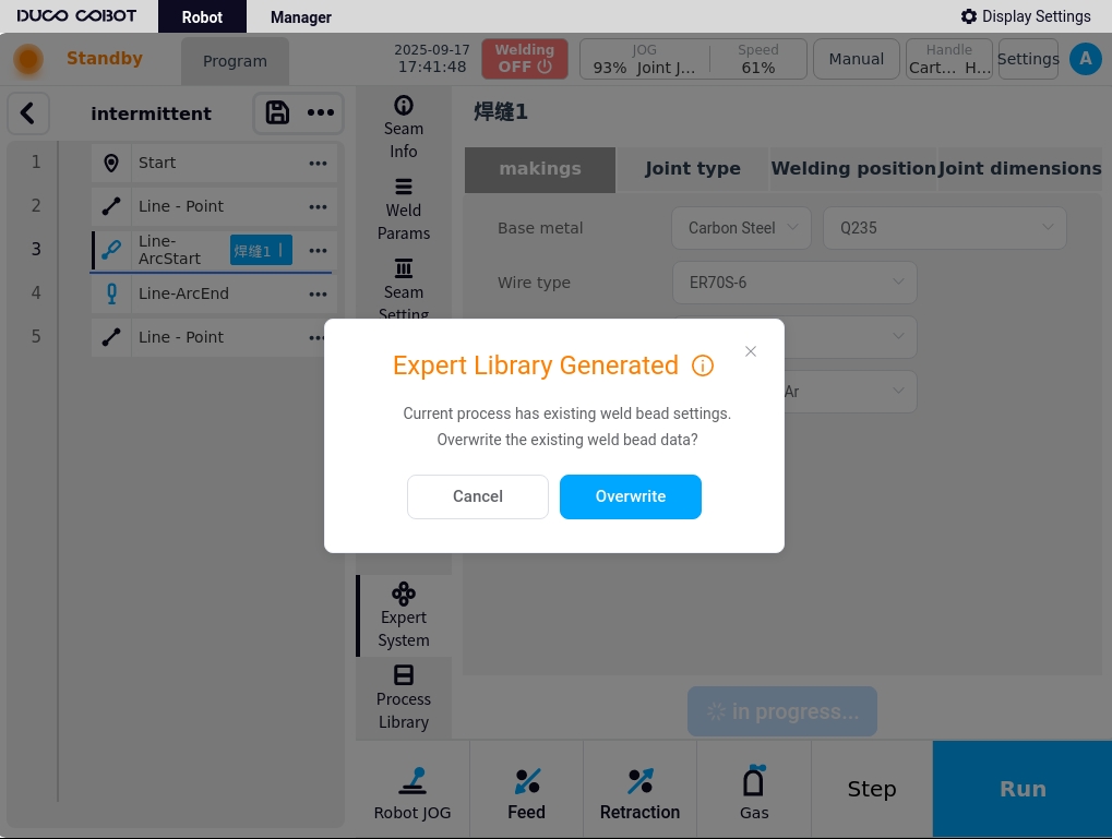
Modify the corresponding weld information by clicking on the ‘Expert System Get Process’ button. The system will generate the corresponding weld path and welding parameters. This is shown below:
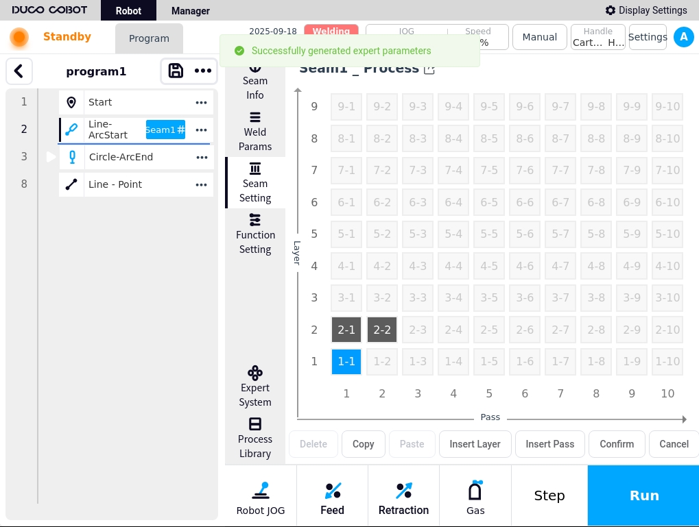
If weld paths and weld parameters already exist for the current process, an indication is given as to whether or not they are to be overwritten.