


Welding execution#
Welding process and welding procedures to understand, you can carry out specific completion of the welding program preparation and implementation; the following will introduce several welding program preparation and implementation.
Programming#
Single-pass welding program#
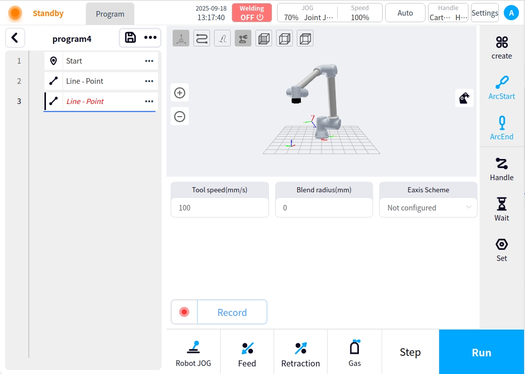
On the Program Management page, click New Program to enter the program editing page;
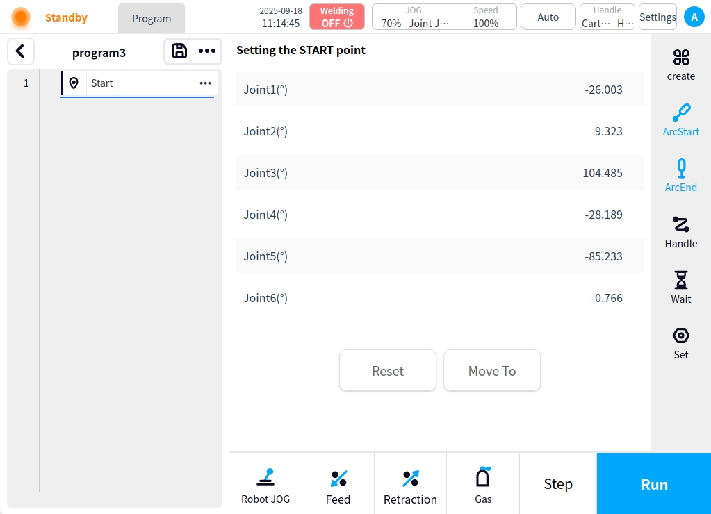
Creating a Start Point Instructs the robot to put the torch in a safe position and create a record start point;
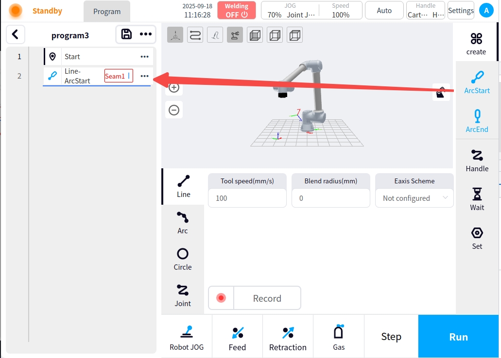
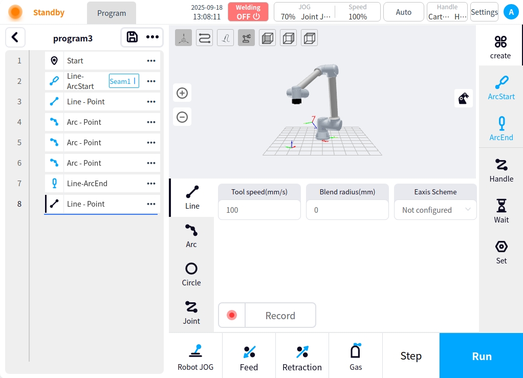
Click the Create button on the right side of the page to add the Linear instructor robot to move the torch to the arc start point and record the current point position;

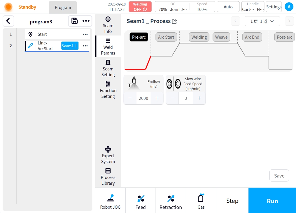
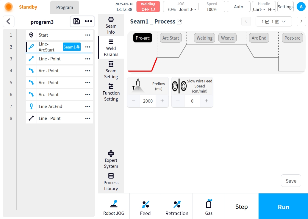
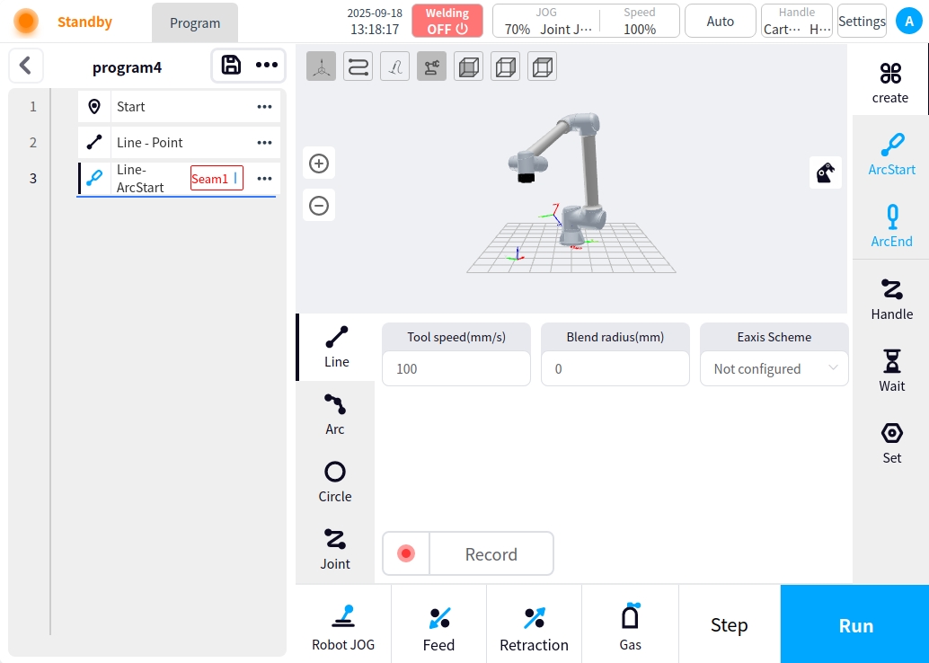
Select the point to start the arc, click the arc button on the right side of the page to make the selected node become the arc point; and click the node on the weld button for welding process settings, welding process settings refer to the program management ` weld process and settings`, weld channel settings need to be set up only a single channel;
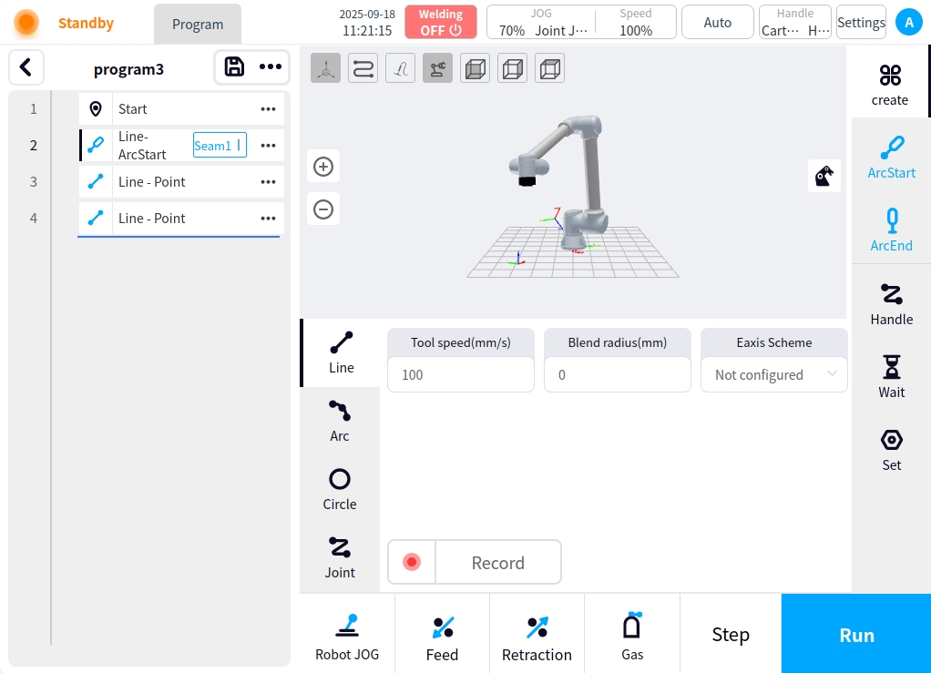
Click on the weld execution type selection on the right side of the page as appropriate, for example:
Straight line + straight line
The intermittent welding method can also be used for linear multi-stage welding or multi-point welding, and the intermittent welding function can be turned on in the welding settings in the process setup`.
Straight line + circular arc or circular arc + circular arc
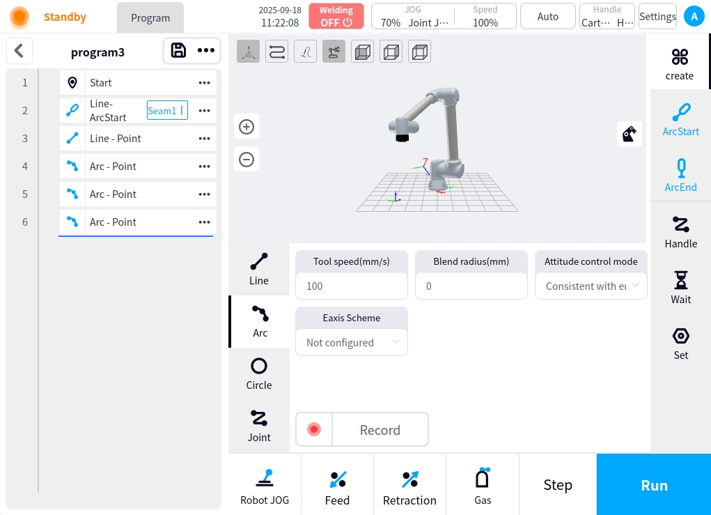
circle
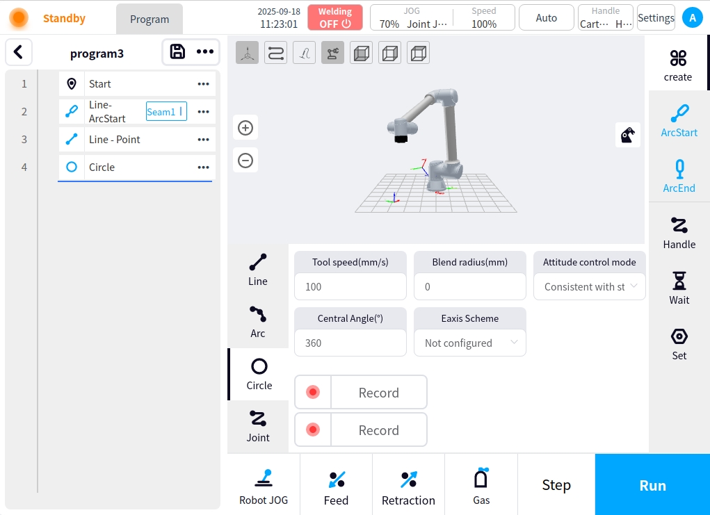
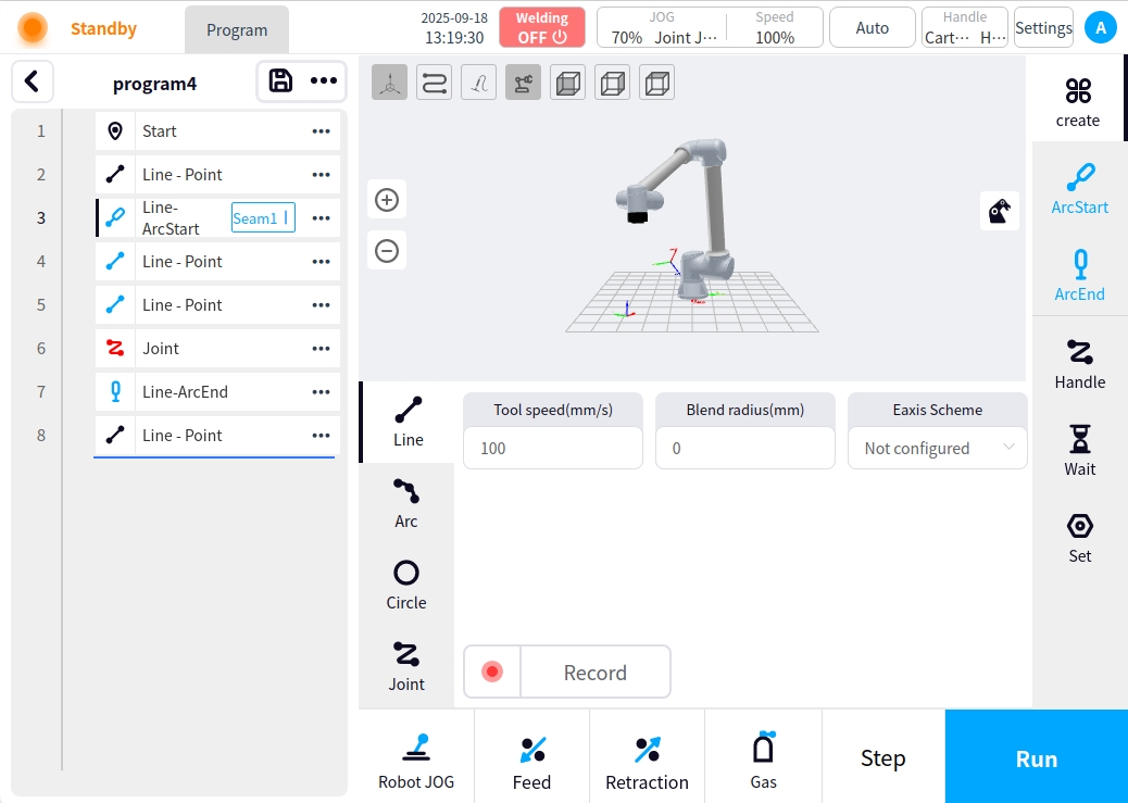
In the arc below the configuration of the seam execution type and trajectory, need to increase the arc node to be considered a complete weld, belonging to the weld all the nodes in front of the icon will turn blue, and in the arc node need to be configured to close the arc under the node of the safety point , in the end of the weld back to the safe position;
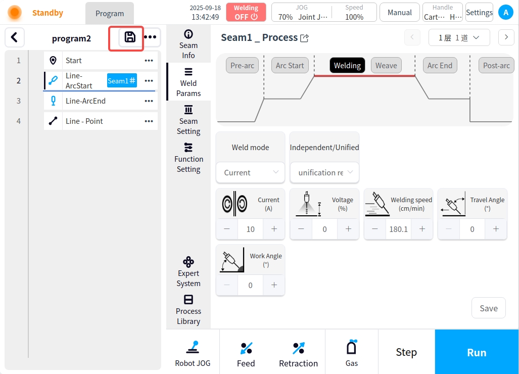
A simple one-pass welding program is now configured. Click on the Save  button at the top of the program node area to complete the single pass weld program;
Procedure for different welding speeds for weld seams#
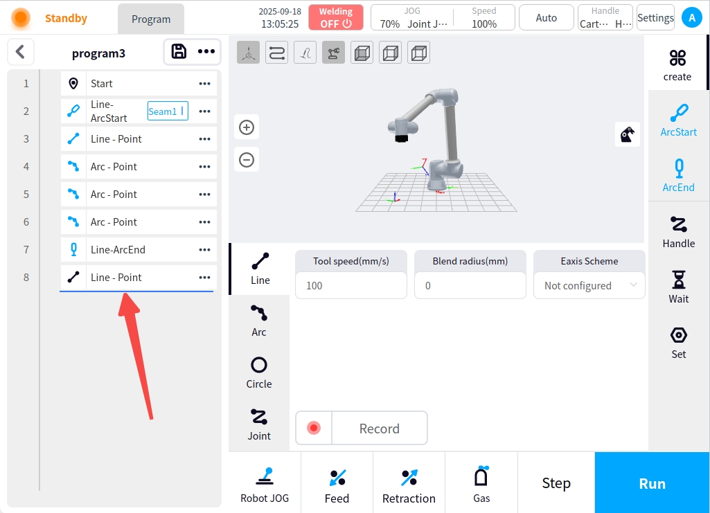
Single weld, different welding speed welding program, need to then close the arc before the creation of multiple arc nodes, arc nodes set up different welding process, for example: change the welding process of welding speed, to achieve a single weld different welding speed requirements, the following chart:
Multiple starting nodes before the closing node will not trigger the starting command repeatedly

Multi-layer, multi-pass welding procedures#
A multi-layer, multi-pass welding procedure is the same as a single pass procedure; the difference is in the process setting of the weld;
Create programs by scene, for example:
Click on the arc welding seam to add multi-layer multi-channel process, if you have added a multi-layer multi-channel process in the process library, it is a direct choice; if you use the expert system to enter the expert system to fill in the relevant welding parameters to generate; if you use a user-defined process to enter the user-defined process to add process data;
Here are only user-defined process examples, process library and expert system reference process library and welding process and settings.
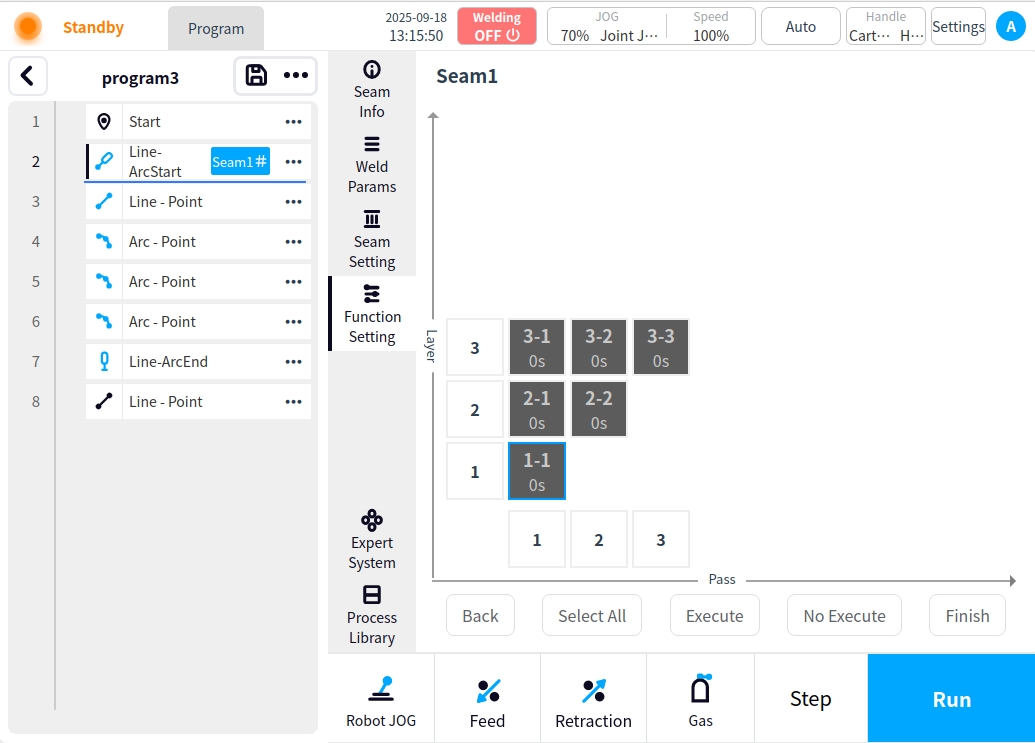
Click the weld button of the arc start node and select Weld Path Setup for multi-layer weld path setup.
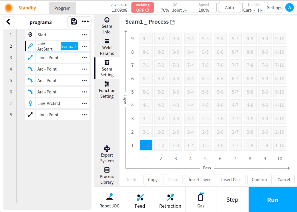
Add weld pass data. For example: one pass for the first layer, two passes for the second layer, and three passes for the third layer.
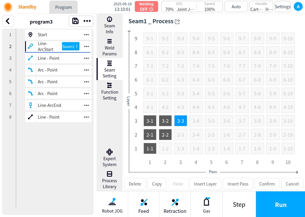
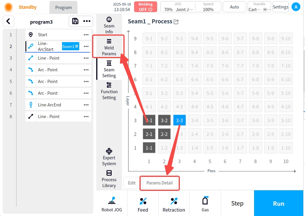
After adding the weld channel, click OK to enter the preview page, in the preview page, you can select the weld channel in the grid, click the Parameter Details button to enter the welding parameter page, or directly click the welding parameter button on the left to enter the welding parameter page.
Example: The first layer of a, as a follow-up weld only need to be in order (before the arc → arc → welding / swing welding → arc closing → arc after) click on the corresponding button to add the relevant weld data can be. When finished, click Save to return to the preview page for other weld pass operations;
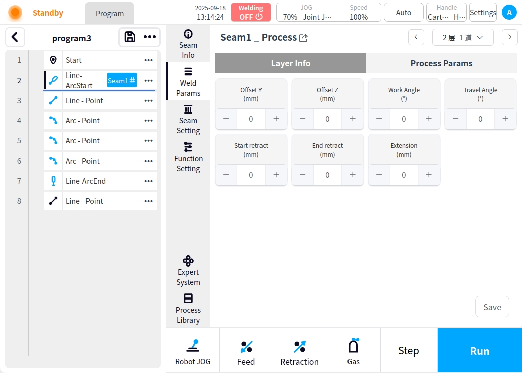
Example: The second layer; non-following welding channel needs to be configured interlayer information. Configure the interlayer information as shown in the figure below, and then click on the process parameters to configure the process parameters after the configuration is completed (refer to the example above).
Subsequent welding channel configuration is the same as above, in order to configure. After configuration, click on the function setting to enter the function setting page, you can turn on the related functions (such as arc tracking, welding protection, multi-layer multi-channel, etc.) according to your needs.
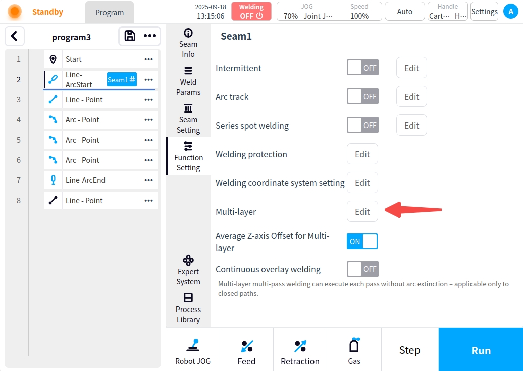
If you need to add I/O inter-channel, inter-channel delay, or perform only part of the weld channel for multi-channel, click the Multi-channel button to configure the multi-channel; (refer to Program Management for the description of Multi-channel setup in the Weld Process and Setup).
After completing the multi-layer multi-pass process settings, click the Save button to complete the multi-layer multi-pass welding program.
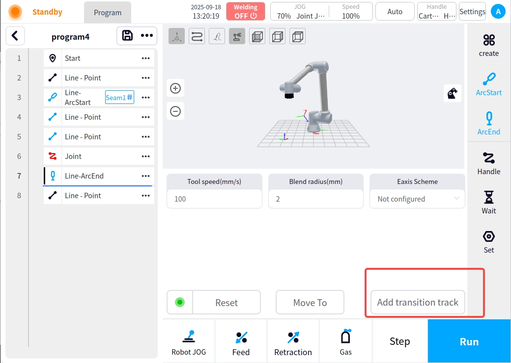
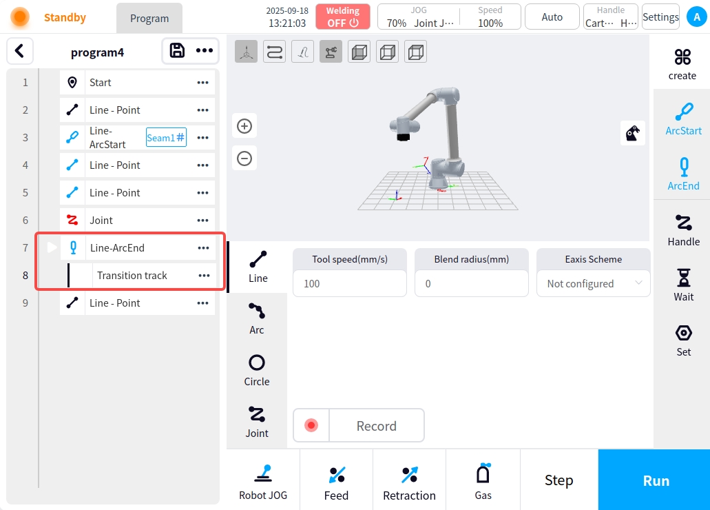
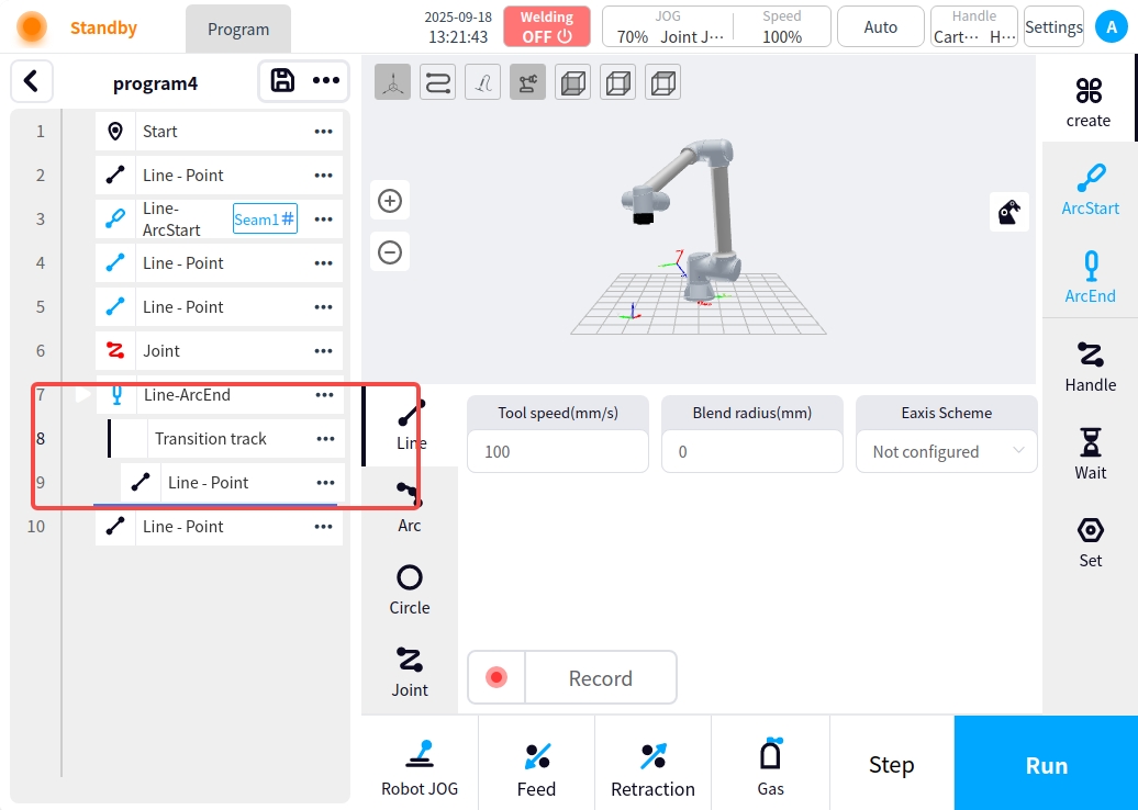
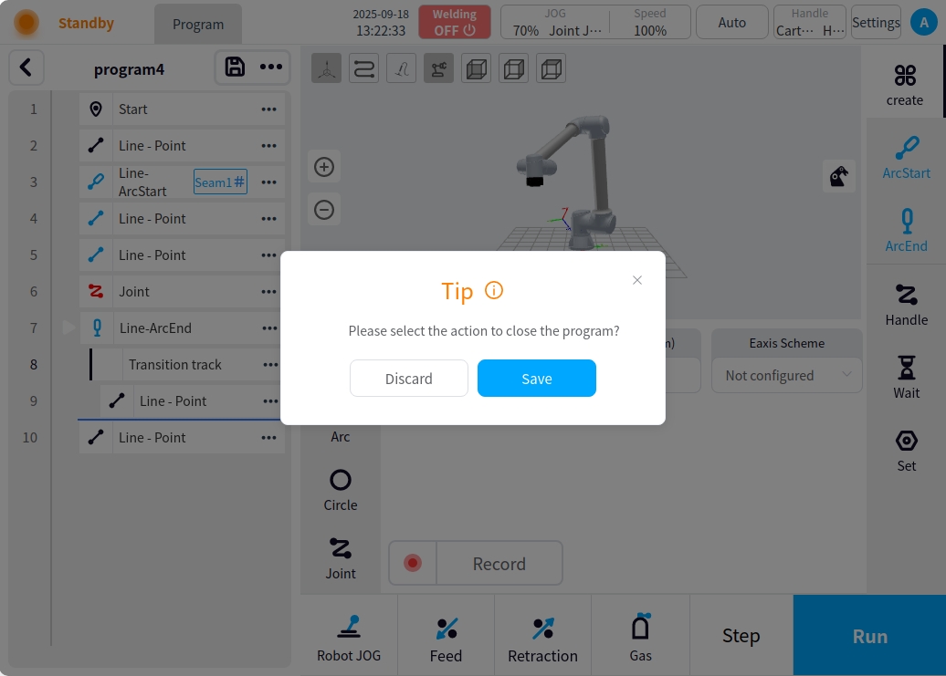
Transition trajectory: In the complex scene of multi-layer multi-channel welding, the transition between channels has to take into account the safety attitude, so it is necessary to set the transition trajectory. Transition trajectory setting mode: 1. The current weld is a multi-layer multi-pass weld. 2; 2. Select the arc closing node in the program, and click ‘Add Transition Trajectory’ in the lower right corner of the arc closing content area; 3. After adding the transition trajectory instructions, click on the right side of the page to create instructions, and then add the corresponding motion trajectory instructions in accordance with the scene can be. For example: add a straight line;
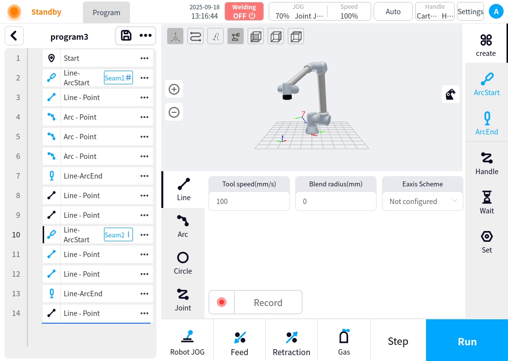
Multi-seam welding program#
In addition to multi-layer multi-pass, you can also add multiple weld seams for welding execution; the program editing method and process addition method remain unchanged, and you can simply create other weld seams by adding arc starting and arc closing, as shown in the figure below:
real time calibration#
During the editing process of the program, the added program nodes are detected in real time whether they are correct or not, and the corresponding prompts are given.
** Points not recorded:** The program node font is skewed and turns red when points are not recorded in a motion instruction. Example:
No process parameter set: When no process parameter is set after adding an arc start command, the weld button font on the arc start node turns red. Example:
Joint Motion Add Error: Adding joint motion commands during welding is not allowed, if you add a joint motion command, the left icon of the joint motion command turns red. Example:
Program return: Program editing state click the top left return button, will pop up ‘please select the operation to close the program’ prompt box, choose to save will save the current program and then return to the list of programs, choose to abandon the changes, then give up the current editing of the program to retain the program before editing the state of the program to return to the list of programs. After opening the current program, if it is edited and saved several times, if you select the Give up Changes button after returning in the editing state, the program retained at this time is the last saved program; no pop-up window in the non-editing state;
program execution#
The program runs as a weld execution. In the non-editing state, click the Run button to start the program running.
Checks before running the program
Before the program is run, the relevant program check will be carried out, and after the check is passed, the program can be saved and run. The check rules are as follows:
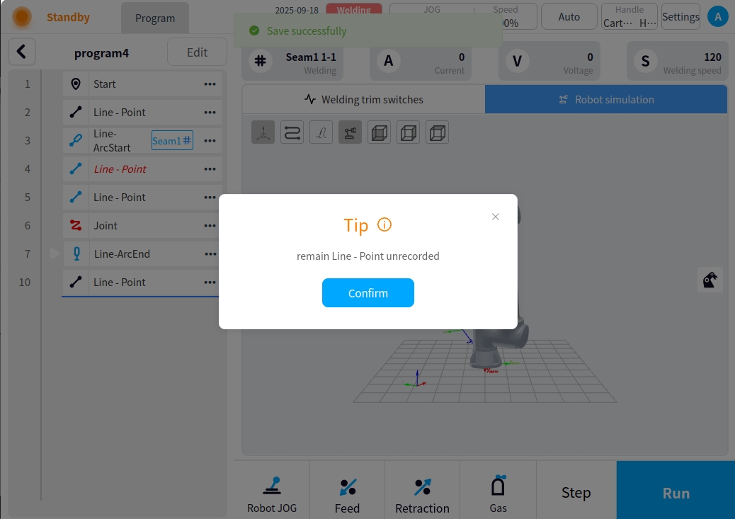
When nodes such as start point, straight line, arc, circle, joint motion, etc. exist in the program, the position of their marked record points must be set. When missing, the calibration fails and a pop-up box prompts, such as the existence of unrecorded straight line points
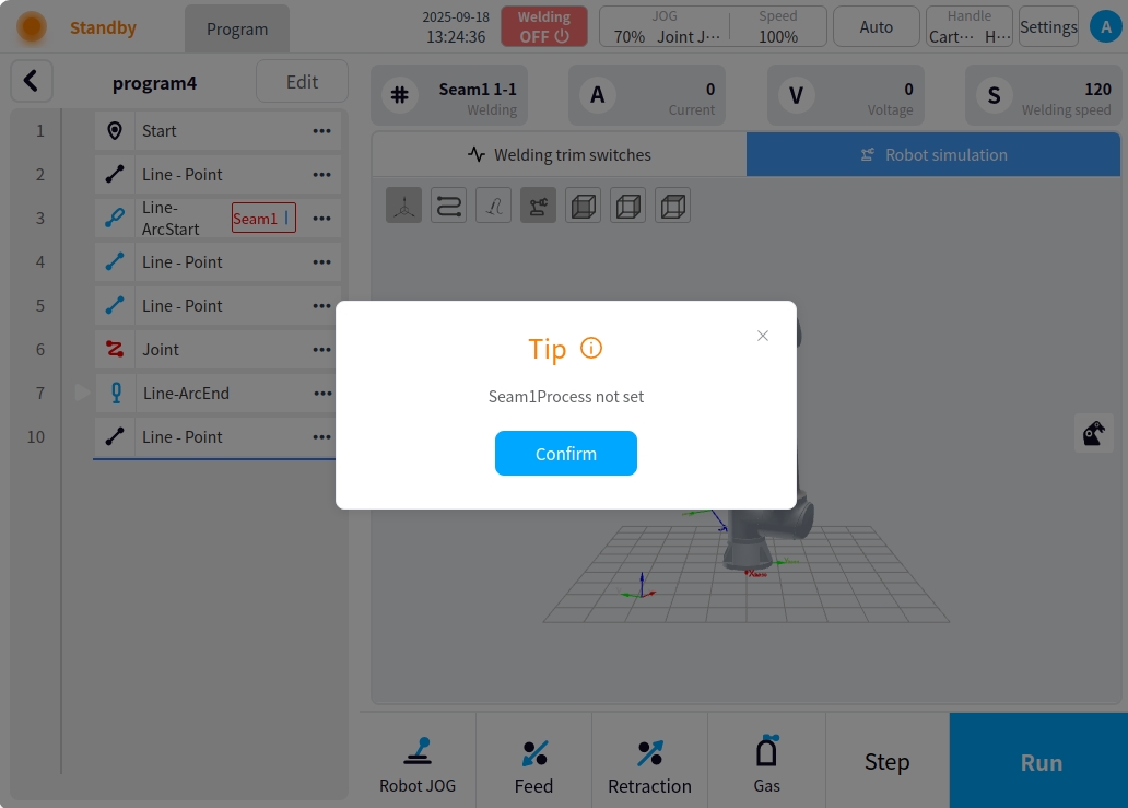
When there is an arc start command in the program, the process configuration of the weld must be configured; if the process configuration is not configured, the verification fails and a pop-up box will be displayed.
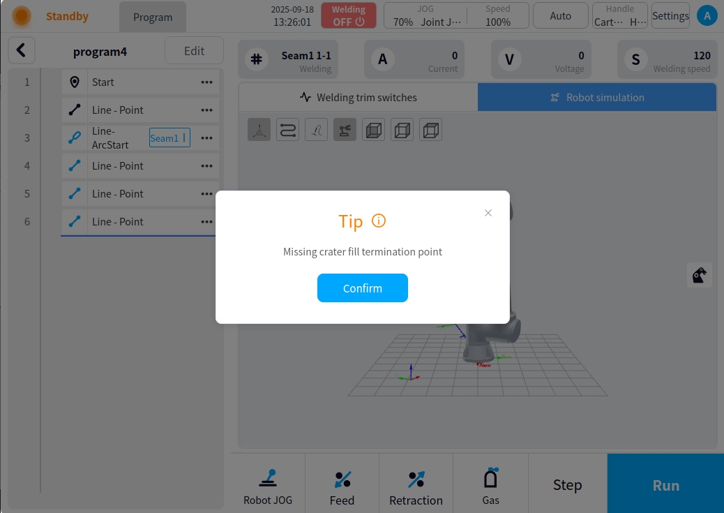
When there is an arc starting instruction in the program, the arc closing instruction and the arc closing safety point must be configured after the arc starting, if not configured, the verification fails and there will be a pop-up box to indicate that

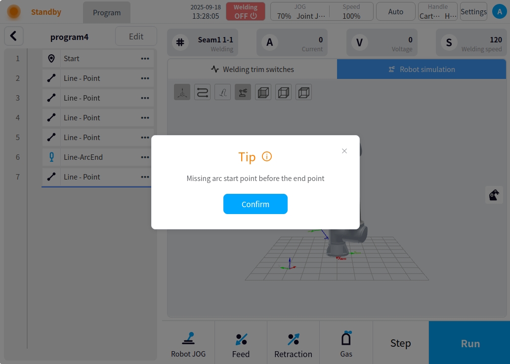
When there is an arc closing instruction in the program, the arc starting instruction must be configured before closing the arc, if it is not configured, the check fails and there will be a pop-up box to indicate that
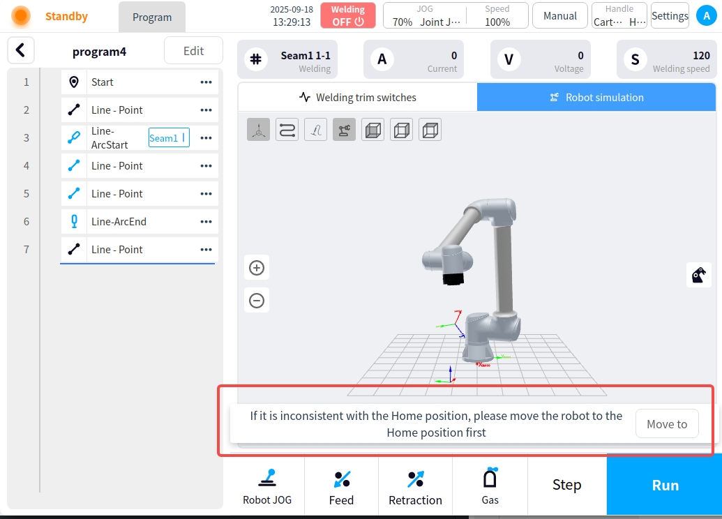
If the current robot attitude point is different from the program start point, a message ‘Not consistent with the Home position, please move the robot to the Home position’ will appear at the bottom of the page, click and hold the start point to return to the start point;
The program runs normally after the program check passes. When the program is running, the page displays the operation status and welding parameters, and provides some operation command functions as follows:
** Display of operating status and welding parameters:**
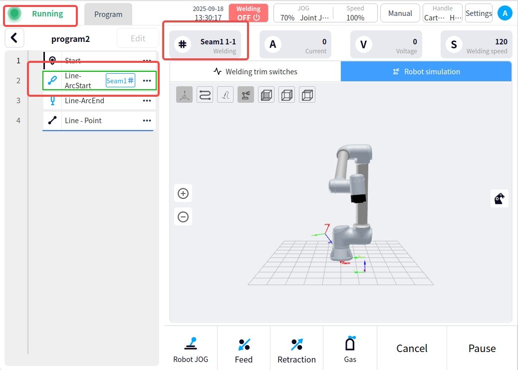
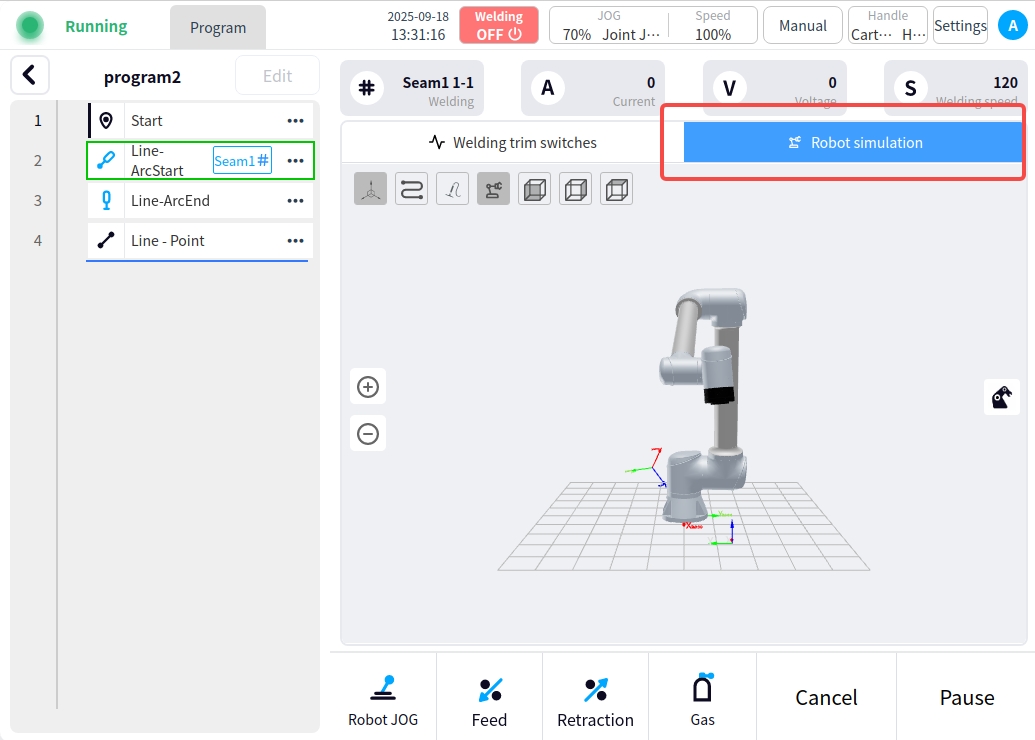
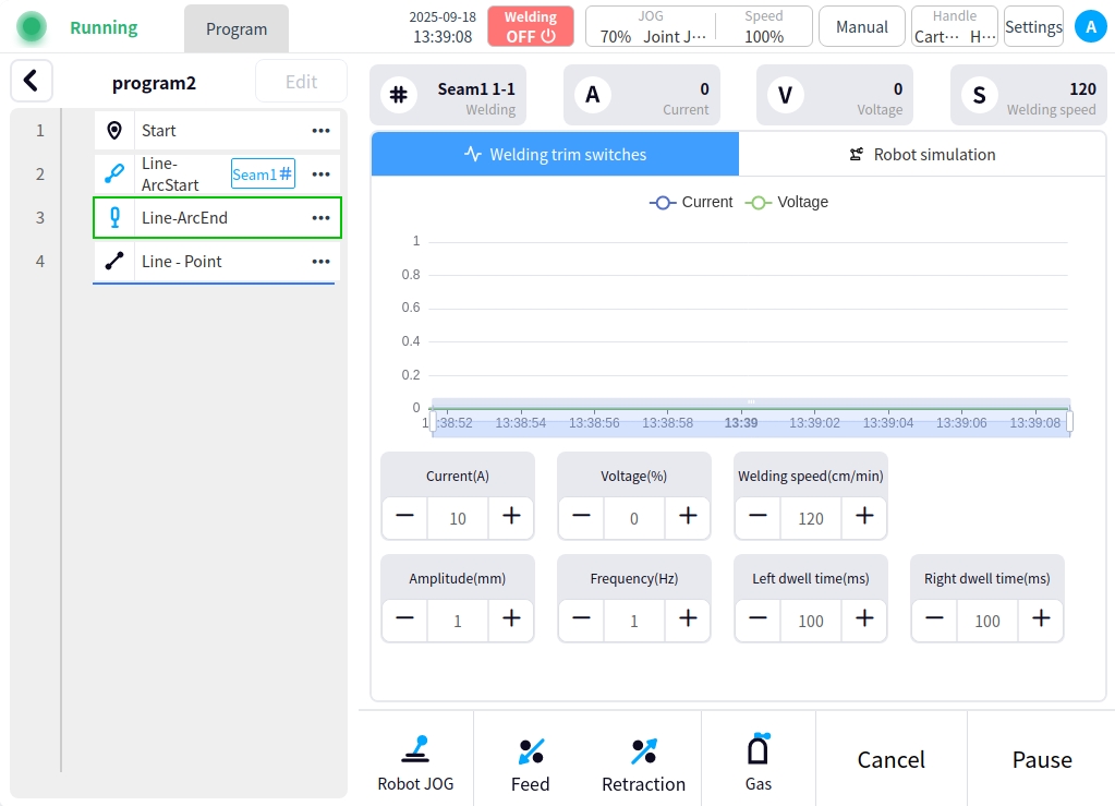
Running status: The robot status in the upper left corner of the page is running, and the left side of the program will be labeled to show the current execution of the trajectory node; the top of the content area will show the current weld seam weld channel; if you need to see the robot running attitude can click on the right side of the page ‘Robot Simulation’ button to switch to the Robot Simulation page;
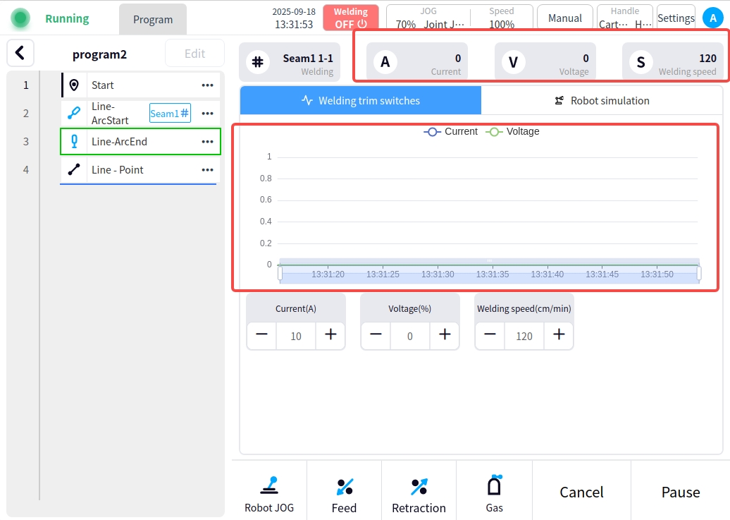
Welding parameter display: the top of the page content area will display the current welding parameter information (current, voltage, welding speed); the middle area will display the current current current and voltage curve fluctuation graph by default;
Operating command function in operation:
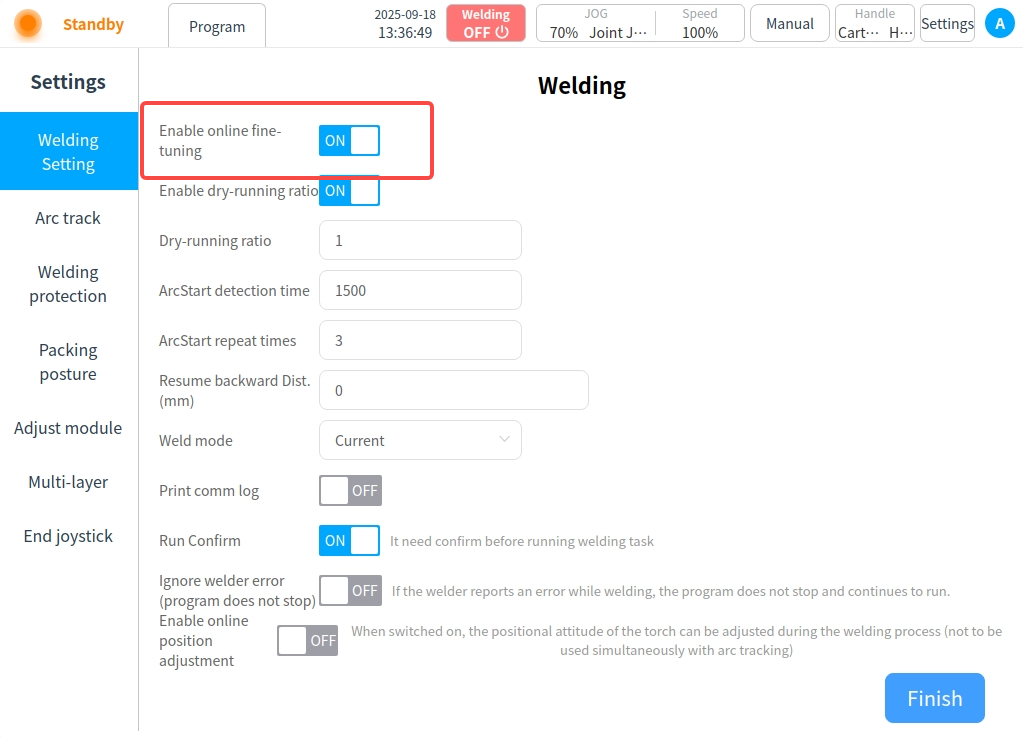
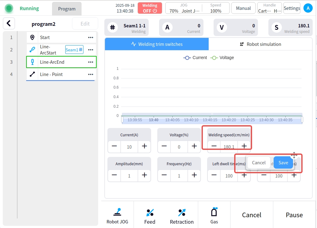
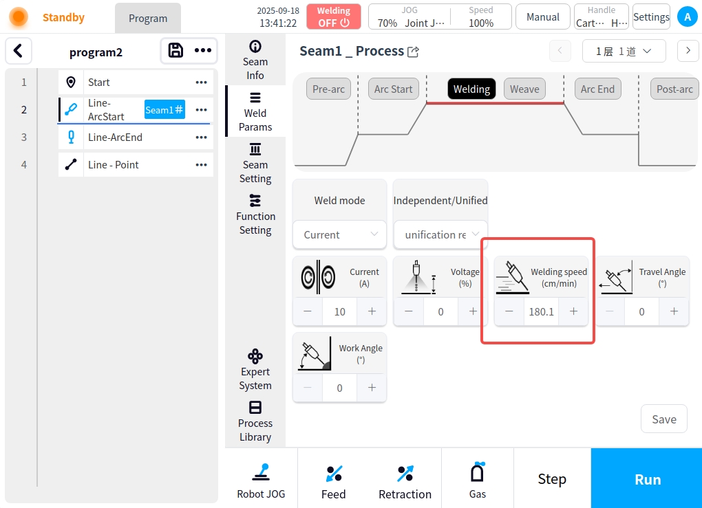
Welding real-time data modification: Click the Setup button at the top of the page to enter the setup page, and turn on the Enable online fine-tuning function in the welding setup; after enabling it, you can fine-tune and modify some of the parameters of the weld in the running of the program; the online fine-tuning must be in the process of the welding trajectory to be able to make modifications; and after the modification, you can choose whether or not to synchronize the modification to the weld process. For example, if you modify the welding speed, a pop-up window with a save button will appear; press and hold the upper right corner of the pop-up window to move; if you save the pop-up window, you can view the modification results in the weld process;
Operational commands: Several operational commands are provided below the content area;

Functional commands: The Functional Commands tool area is, from left to right:
Move: Enter the robot move page, in the move page you can click the corresponding button to move operation; you can also click the move to button to input the corresponding joint angle to move operation;
Feeding: Manipulates the wire feeder for wire feeding operations;
Harvesting: Manipulates the wire feeder to perform the harvesting operation;
Air feeding: Operate the welder for air feeding operation;
Operating instructions:
Stepping: The program runs in a stepping mode;
Run: Run the program;
Cancel: Click the Cancel button to close the current welding task;
Pause: Click the Pause button to pause the current welding task;
Continue: While paused, click the Continue button to continue the current welding task;